Table of Contents
Advertisement
Advertisement
Table of Contents

Related Manuals for Leica TPS 1000 Series

Summary of Contents for Leica TPS 1000 Series
- Page 2 TPS - System 1000. This manual contains important safety directions (refer to chapter "Safety directions") as well as instructions for setting up the instrument and operating it. Read carefully through the User Manual before you switch on the instrument. TPS-System 1000-2.3.1en © Leica...
- Page 3 © Leica The instrument model and the serial number of your product are indicated on the label in the battery compartment. Enter the model and serial number in your manual and always refer to this information when you need to contact your agency or authorized service workshop.
- Page 4 / or appreciable material, financial and environmental damage. Important paragraphs which must be adhered to in practice as they enable the product to be used in a technically correct and efficient manner. TPS-System 1000-2.3.1en © Leica...
- Page 5 Act immediately Complete and return part 2 to ensure that you receive software support. If you do not, you will not be registered and Leica will not be able to provide the support that you may need. Software support Once your name, your address and the serial number of...
- Page 6 Limit to software support Once your name, address and instrument are registered Leica undertakes to provide reasonable support for the software as supplied to you. This software support does NOT extend to upgrades to new versions of software as may be introduced by Leica in the future.
- Page 7 (Please write clearly or use the Company stamp) Contact persons Telephone Telefax © Leica Please fill in the coupon below and send the original or a copy to the address on the other side or fax it to +41 71 727 3605.
- Page 8 " Software-Support Registration Geodesy Division (3681) Leica Geosystems AG CH-9435 Heerbrugg Switzerland TPS-System 1000-2.3.1en © Leica...
- Page 9 © Leica Contents Introduction Instrument descriptions Preparing to measure, setting up First steps System concept Operating concept Instrument operation Automatic Target Recognition RCS (Remote Controlled Surveying) Guide Light EGL1 Checking and adjusting Care and transport Battery charging Data format Safety directions...
- Page 10 First steps Switching on the instrument Levelling-up with the electronic bubble Installing a distancer (EDM) Measuring distances and angles Summary of the first steps System concept Software architecture Memory concept and data flow Operating modes GeoBasic TPS-System 1000-2.3.1en © Leica...
-
Page 11: Table Of Contents
© Leica Operating concept Display / keyboard Types of dialog Program-selection dialog Input/output dialog Character field Numeric field List field Two-value field Heading Time Battery display Graphical status icons Function keys Fixed keys Control keys Enter keys Menu tree (Main menu after ON) - Page 12 Data management Entering coordinates Deleting data View data Edit data Leica prisms and retro tapes Prism for attachable EDM Prism for incorporated EDM The GRZ4 360° reflector Leica retro tapes Summary Long distances Extra On-line mode Format a memory card...
- Page 13 © Leica RCS (Remote Controlled Surveying) Introduction Setting up Allocation of keys Working procedure Compass Hz / V Joystick Lock interruption Last point stored Guide Light EGL1 ON / OFF Checking and adjusting Electronically Compensator (electronic bubble) V-index error Line of sight...
- Page 14 Laser plummet (only Txx xxxxL) Electromagnetic acceptability FCC statement (applicable in U.S.) Product labeling Technical specifications Technical specifications of the Automatic Target Recognition ATR1 Technical specifications of the EGL1 Guide Light Application programs Atmospheric corrections Index TPS-System 1000-2.3.1en © Leica...
- Page 15 PCMCIA card for data storage. The data structure is compatible with previous and other current Leica total stations and electronic theodolites. This permits data interchangeability with Leica GPS - Systems. Individual application programs are available or can be written by the user.
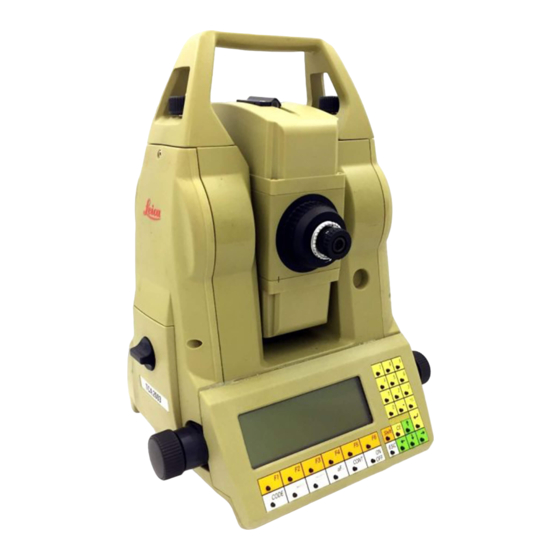
- Page 16 General text applies to all types. General illustrations represent the TCA 1800 instrument with EGL1 guide light option and apply to all models. The present User Manual is valid for the software version 2.2. TPS-System 1000-2.3.1en © Leica...
- Page 17 © Leica 9 10 1 Footscrew 2 Keyboard 3 Display 4 Optical sight 5 Carrying handle 6 Telescope 7 Vertical drive screw 8 Vertical clamp 9 Horizontal drive screw TPS-System 1000-2.3.1en 15 17 10 Horizontal clamp 11 Battery housing 12 Tribrach securing...
- Page 18 6 Telescope 7 Vertical drive screw 9 Horizontal drive screw TPS-System 1000-2.3.1en 15 17 11 Battery housing 12 Tribrach securing knob 13 Circular level 14 Memory card housing 15 Focusing ring 16 Interchangeable eyepiece 17 Adapter for attaching © Leica...
- Page 19 © Leica 1 Footscrew 2 Keyboard 3 Display 4 Optical sight 5 Carrying handle 6 Telescope with integrated EDM 7 Coaxial optics for angle- and distance measurement 8 Vertical drive screw 9 Vertical clamp TPS-System 1000-2.3.1en 10 Horizontal drive screw...
- Page 20 7 Coaxial optics for angle- and distance measurement TPS-System 1000-2.3.1en 10 11 8 Vertical drive screw 9 Horizontal drive screw 10 Battery housing 11 Tribrach securing knob 12 Bull's-eye bubble 13 Memory card housing 14 Focusing ring 15 Interchangeable eyepiece © Leica...
- Page 21 © Leica 18 6/16 7 1 Footscrew 2 Keyboard 3 Display 4 Optical sight 5 Carrying handle 6 Telescope with integrated EDM 7 Coaxial optics for angle- anddistance measurement with EGL1 Guide light (Option) 16 EGL1 Guide light 17 Flashing left diode (yellow) 18 Flashing right diode (red) TPS-System 1000-2.3.1en...
- Page 22 4 Memory card (optional) 5 Plummet (optional) 6 Cable (optional) 7 Eyepiece for steep angles (optional) TPS-System 1000-2.3.1en 8 Zenith eyepiece (optional) 9 Allen key 10 Screwdriver, set pin 11 Interchangeable eyepiece (optional) 12 Spare battery (optional) 13 Shoulder straps © Leica...
- Page 23 GEB87 © Leica Charge batteries using GKL12, GKL14, GKL22 or GKL23. For more information about charging batteries refer to chapter "Battery charging". ‚ GEB87 ‹ GKL23 ( Œ GKL23-1 ( Charging time: 1.5 hours External batteries: GEB70: 1.5 hours GEB71: 5.0 hours...
- Page 24 EDM is above the telescope, otherwise distances may be reduced wrongly. When the theodolite is used in conjunction with the EMD models DI1001, DI1600, or DI2002, we recommend using the GPH1A single-prism holder for measuring over short distances. GPH1A single-prism holder TPS-System 1000-2.3.1en © Leica...
- Page 25 © Leica The height difference between the telescope's optical axis and the infra-red beam is corrected by the corresponding difference at the target, therefore aim the crosshairs at the yellow target mark. For instruments with built-in EDM, no preliminary adjustments to the EDM are required before use.
- Page 26 GDF 22 ... tribrach GST20 ... tripod 1. Set up the GST20, centring it as well as possible. 2. Using the footscrews of the GDF22, centre the plummet to the ground point. TPS-System 1000-2.3.1en 5/8"thread GDF 22 GST20 © Leica...
- Page 27 © Leica 3. Move the legs of the tripod to centre the bull’s-eye bubble. 4. Level-up precisely, using the electronic bubble (see the chapter "Levelling-up with the electronic bubble"). 5. Centre exactly by shifting the GDF on the tripod plate.
- Page 28 5. Centre exactly by shifting the GDF on the tripod plate. Repeat steps 4 and 5 until the required accuracy is attained. TPS-System 1000-2.3.1en 2. Centre by moving the tripod legs. 3. Move the footscrews of the GDF21 to centre the bull’s-eye bubble. © Leica...
- Page 29 1. Set up the GST20, centring it as well as possible. © Leica The laser plummet is built into the standing axis of the "L" versions of the TPS1000 instruments. A red dot projected on the ground makes it much easier to centre the instruments.
- Page 30 4. Level-up precisely, using the electronic bubble (see the chapter "Levelling-up with the electronic bubble"). 5. Centre exactly by shifting the GDF on the tripod plate. Repeat steps 4 and 5 until the required accuracy is attained. TPS-System 1000-2.3.1en © Leica...
- Page 31 Set up in accordance with the chapter "Setting up the instrument". Switch on. GSI-Version 2.22a <C> Leica AG, 1994-97 After switching on, the instrument type and the software version are briefly displayed. The display automatically jumps to the main menu. Depending on the configuration, it is also possible to start an application automatically (see chapter "Configuration").
- Page 32 In the display which is closest to the bull's-eye bubble, the movement of the small circle runs parallel to the movement of the bubble in the alhidade. The other display shows the movement in the opposite direction. TPS-System 1000-2.3.1en 14:03 14:03 © Leica...
- Page 33 © Leica Only for T- and TM-Versions with attached EDM: The type of EDM used must be entered in the system. Choose the user configuration. CONF\ SYSTEM CONFIG. 1 System date and time 2 Define functionality 3 GSI communications param.
- Page 34 EDM axis) and the wavelength are automatically set. The correction of the EDM offset can be turned on and off in the option target point (see chapter "Target-point data"). Leaves the "EDM SELECTION" menu. TPS-System 1000-2.3.1en 14:03 DI1001 40.9mm 850nm LIST © Leica...
- Page 35 © Leica Select "MEASURE MODE (GSI)" from the main menu. In the measuring dialog, distances can be measured, angles displayed, point numbers entered and data recorded. MEAS\ MEASURE MODE (GSI) Point no. Remark 1 Refl.Height : Horiz.Dist. : DIST Height diff:...
- Page 36 Once measured, the horizon- tal distance is displayed on the bottom line. Measuring with connected EDM (T- and TM-versions) is to be performed only when the EDM is above the telescope, otherwise distances may be reduced wrongly. TPS-System 1000-2.3.1en © Leica...
- Page 37 © Leica The TPS1000 series includes many different instruments: electronic theodolites and total stations of various accuracy classes, with or without motorization, and total stations with automatic targeting. All of these models use the same software architecture and the same concept for data storage and data flow.
- Page 38 The structure of the directory on the MC is fixed. It includes two subdirectories for the TPS1000: \GSI \LOG The directory \GSI includes files in the GSI data format (see chapter "Data format"). TPS-System 1000-2.3.1en © Leica...
- Page 39 © Leica A distinction is made between: • Input data, generally fixed-point coordinates • Output data, generally measurements, coordinates, or derived values relating to "new points". It is advisable to store the input and output data in two separate files, although it is possible to store them together in a single file.
- Page 40 (ATR). For more information, please refer to "WILD Instruments On-Line" (document no. G-366-0en), a copy of which is available (in English only) from your local Leica agency. • The GeoCOM command set governs complex operations in the TPS1000 instruments and is to be preferred for the professional development of control programs.
-
Page 41: Operating Concept
© Leica The TPS1000 system is organized into various functions, which are started via the function keys in the main menu or via the hard keys. The use of loadable applications can meet specific user requirements, which are then called up from the list of applications in the main menu. -
Page 42: Display / Keyboard
The graphical display is arranged with 8 lines of 35 characters. Graphics can be displayed with a resolution of 64 x 210 pixels across the full display area. TPS-System 1000-2.3.1en Status icons Input keys 14:03 • +/- SETUP MEAS Shift CE CONT Running Control keys info-bar © Leica... -
Page 43: Types Of Dialog
Program-selection dialog © Leica To give an overall view, several types of dialog are used. The input procedure is the same within all types of dialog, promoting ease in use. The following examples illustrate the types of dialog used in the TPS1000. -
Page 44: Input/Output Dialog
In general there is a simultaneous jump back to the previous dialog. TPS-System 1000-2.3.1en 14:03 ----- 0.000 m 295°22'40" 91°20'30" ñ ----- m TARGT the cursor bar can , this concludes © Leica... - Page 45 © Leica Fields in the input dialog The input of all sorts of information is supported by several types of input fields. The input procedure is the same within all types of dialog, promoting ease in use. If the type of input field is not clear, it can be...
-
Page 46: Character Field
The function keys are assigned with alphabetic characters in all cases. With an additional function key an alphabetic character is assigned to each individual function key and can be selected directly. TPS-System 1000-2.3.1en 14:03 ----- 0.000 m 295°22'40" 91°20'30" ñ ----- m TARGT © Leica... - Page 47 © Leica ABCDE FGHIJ KLMNO PQRST UVWXY Z[\] The following display appears: are now assigned individual characters which can be chosen. Additionally, the to select the complete ASCII character set a block at a time. Possible blocks of characters: ABCDE FGHIJ KLMNO PQRST UVWXY Z[\] abcde fghij klmno pqrst uvwxy z{|} Çüéâä...
- Page 48 In a numeric field the insert mode is also called with . The insert mode remains active until it is deactivated with or until quitting the field. TPS-System 1000-2.3.1en -key if a function key © Leica...
- Page 49 Numeric field © Leica -key is assigned with "EDIT". MEAS\ MEASURE MODE (GSI) Point no. Remark 1 Refl.Height: Horiz.Dist.: DIST All entries requiring numeric input (e.g. point coordinates) are of this type. The permitted number of digits, the decimal place etc. are all assigned automatically, and the units used are indicated.
-
Page 50: List Field
The following display shows a typical example for an opened list field: SETUP\ START-UP DISPLAY Select user Polar (Standard) User templ. Rec. device Meas. file Polar+cartesian Data file Selects. Confirm selection. TPS-System 1000-2.3.1en -key when the symbol 14:03 QSET LIST 14:03 Cartesian User 4 © Leica... - Page 51 © Leica In numeric list fields, and in some alphanumeric ones, an entry can be called directly by keying-in the value instead of using CONF\ GSI COMMUNICATION Set GSI com Baud rate Protocol Parity Terminator Data bits Example: Keying-in "1" marks the baud rate (19200)
-
Page 52: Heading
The time as used by the system. The correct time is maintained, even when the main battery is removed, by an internal back-up battery. TPS-System 1000-2.3.1en 14:03 loud 90°00'00" àON 14:03 ----- 0.000 m 295°22'40" 91°20'30" ñ ----- m TARGT © Leica... -
Page 53: Battery Display
© Leica When the battery is fully charged the battery display is seen also to be full. As the battery is discharged, the display records this in 4 increments. Battery fully charged Battery almost fully charged Battery still capable of being used Battery reserve power. - Page 54 Compensator or Hz-correction has been disabled. The compensator functions normally and the Hz directions are corrected. Telescope face display field Displayed only in measuring mode. Face 1 Face 2 TPS-System 1000-2.3.1en © Leica...
- Page 55 © Leica Automatic target recognition Automatic target recognition is activated. Automatic target tracking (LOCK) is activated, but no prism has been targeted or lock to prism has been lost. LOCK is activated, target is tracked. Lock to prism has been lost. Search is in progress.
- Page 56 This is the "HELP" key for every dialog. Here the functionality of the current dialog is briefly described. Aborts a function or application and returns to the main menu. All entries in the last dialog of the function or application are rejected. TPS-System 1000-2.3.1en Shift © Leica...
-
Page 57: Fixed Keys
© Leica CODE aF... CONT Fixed keys (white) The functions associated with these keys are available at all times. These keys bypass the current operation sequence to access a system function, returning to exactly the same display afterwards. Calls code input. See chapter "Code information". -
Page 58: Enter Keys
Input in numerical fields, or selecting and starting of functions with a related number. Decimal point and sign. Confirms the input within a line or the choice from a list. Deletes the last digit or letter entered. TPS-System 1000-2.3.1en • +/- © Leica... - Page 59 EXTRA CONF © Leica Help functions On-line mode (GeoCOM) Format the memory card Remote Control Mode (only TCA-Versions) Display and determination of instrument errors Determine the compensator index errors (l,t) Determine the vertical index error (i) Common determination of errors for the line of sight (HZ-...
- Page 60 Select individual or running point number Hz-circle orientation Display last recorded point number Positioning in the other face Calls list of on-board application programs Select existing code function, enter a code block Coloured field not accessible when in reduced functionality mode TPS-System 1000-2.3.1en © Leica...
-
Page 61: Main Menu
© Leica After the instrument has been switched on, the instrument model and software version are briefly displayed. The instrument carries out a system test and then engages the main menu. The special significance of the main menu is that all... - Page 62 Data- and file management. See chapter "Data management". Input of station data and orientation, selection of user template and measurement file. See chapter "Set station data". Measurement and recording. See chapter "Measurement and recording". TPS-System 1000-2.3.1en 14:03 DATA SETUP MEAS © Leica...
-
Page 63: Fixed-Key Occupation
© Leica A code block with additional information is defined and recorded. In general, the key is activated when measurements or coordinates can be recorded for a point. For details, see chapter "Code information". Various illuminators can be switched on, and the brightness adjusted. - Page 64 - Entering the refraction coefficient - Recalling the last point number to be recorded - Changing the telescope face - Entering manually-determined horizontal distances - Incrementing the point number - Switching from current- to other point numbers. TPS-System 1000-2.3.1en © Leica...
- Page 65 © Leica MEAS\ MEASURE MODE (GSI) Point no. Remark 1 Refl.Height : Horiz.Dist. : DIST Height diff : Easting Northing Elevation HELP LAST The data shown above represent the standard display template. Distance measurement and measurement-block recording. The recorded measurement block corresponds to the active recording template.
- Page 66 (TM/TCM- and TCA versions). Calls the application programs dialog. From here, the application programs can be started. Explanation of the elements of measurement Instrument height Hz = Horizontal angle V = Vertical angle TPS-System 1000-2.3.1en Reflector height Height difference © Leica...
-
Page 67: Measuring Distances And Angles Together
Measuring distances and angles together © Leica Simultaneous measurement and recording. MEAS\ MEASURE MODE (GSI) Point no. Remark 1 Refl.Height : Horiz.Dist. : DIST Height diff : Easting Northing Elevation HELP LAST Hz-angle measurement is carried out after the distance has been measured. - Page 68 It is therefore possible to record inaccessible points, e.g. house corners, fences surrounded by hedges. Storing DATA TPS-System 1000-2.3.1en 14:03 ----- 1.500 m 214°52'45" 85°25'17" ñ 100.251 m TARGT 23.650 m 76.943 m 1902.437 m 523.650 m I<>II PROG © Leica...
- Page 69 © Leica For calculations which depend on distance, the V- angle after completion of the distance measurement is used, along with the current Hz-direction. Consequently, calculated heights and height differences are retained and the coordinates for easting and northing which correspond to the new Hz direction are recalculated using the last-measured distance.
-
Page 70: Target-Point Data
Remark 2 Remark 3 PRISM D INP OFFS Remark 4 Remark 5 Remark 6 Remark 7 Remark 8 Remark 9 HELP TPS-System 1000-2.3.1en 14:03 102001 12A20001 1.500 m ----- ----- ----- INDIV ----- ----- ----- ----- ----- ----- © Leica... -
Page 71: Remarks
Remarks © Leica Choose the prism from 6 possibilities : Leica circular prism, retro tape target (not in the T/TM versions), Leica 360° prism, 3 user-defined prisms. Setting the atmospheric ppm and the geometric ppm (height and projection) and the refraction coefficient. -
Page 72: Incrementing Point Numbers Ca
Overflow of running point no. after incrementation. Check point no. Confirms the warning and the change in the point number or in the increment. TPS-System 1000-2.3.1en 14:03 102001 12A20001 1.500 m ----- ----- ----- INDIV 12Az100 1001000 No transfer of letters 14:03 © Leica... -
Page 73: Set And Define Prisms
EDM axis and the telescope axis. When using the tilting Leica prism GPH1A this correction is not necessary and must therefore be disengaged. Choose the Leica circular prism (standard setting). - Page 74 Choose Leica retro tape. The EDM is switched into a mode in which it can measure to retro tape targets. Simultaneously, the corresponding prism constant is set. T/TM-versions with attachable EDM cannot measure to retro tapes. Choose the Leica 360° prism. The corresponding prism constant is set automatically.
- Page 75 Reduced input of ppm values © Leica Prism type: The symbol of the prism type indicates whether the reflector is to be treated as a prism or as a retro tape. Move the cursor bar to the column "PRISM" The reflector is set as a prism.
-
Page 76: Comprehensive Distance Corrections (Ppm)
Set the atmospheric ppm to "0.00". (Individual parameters are set to the standard atmospheric values, corresponding to the atmospheric correction ATM=0) The dialog is dependent on the setting within "FUNCTIONALITY". TPS-System 1000-2.3.1en 14:03 12.0 °C 1013.3 mBar %<>T' ATM=0 EDIT EDIT © Leica... - Page 77 © Leica • Geometrical correction The geometrical distance correction is derived from the projection distortion and the height above the reference datum. The calculation of the geometrical ppm follows the formula for the Transversal Mercator Projection. The individual factors are: the scale factor of the line of projection (central meridian, Gauss-Krüger = 1.0,...
- Page 78 Both methods calculate the same result with different input values. 1 - k Method 1: ( Standard value k = 0.13 ) 0.5 - Method 2: ( Standard value k = 0.07 ) TPS-System 1000-2.3.1en 14:03 0.13 Method 1 DEFLT EDIT © Leica...
- Page 79 Manual distance entry © Leica Enter the horizontal distance, which was measured with a tape for instance. Immediately after confirmation of input, the horizontal distance is shown corrected for the geometrical ppm. After the distance has been entered, the V-angle is set to "horizontal"...
-
Page 80: Target Eccentricity
Activates the function "OFFS" in the dialog "Target- point data". MEAS\ OFFSET DATA Enter offset data Shft length: Shft trans : Shft height: HELP Shft trans (+) Centre TPS-System 1000-2.3.1en 14:03 0.000 0.000 m 0.000 m DEFLT EDIT Shft height (-) © Leica... -
Page 81: Individual Point Number
Individual point number © Leica MEAS\ TARGET DATA Increment Runn. PtNo : Refl.Height : Remark 1 Remark 2 Remark 3 PRISM D INP OFFS HELP Toggles between running ("RUNN") point number and individual ("INDIV") point number. TPS-System 1000-2.3.1en 14:03 102001 12A20001 1.500 m... -
Page 82: Select User Template And Measurement File
A known direction to a tie point can be entered. Activates the function "STN" from the dialog "START- UP DISPLAY". SETUP\ STATION DATA Station no.: Inst.Height: Stn.Easting: Stn.Northng: Stn.Elev. HELP TPS-System 1000-2.3.1en 14:03 STAT LIST 14:03 1.520 m 100.000 m 2000.000 500.000 m ñ 222°42'33" IMPOR VIEW © Leica... - Page 83 © Leica After the point number of the station point has been entered, the coordinates can be input directly using the numeric keys or can be imported from the data file of the memory card. Recording station data The station data (point number, easting, northing,...
- Page 84 The dialog "STATION DATA" is an exception to this rule and the coordinates there are displayed. TPS-System 1000-2.3.1en 14:03 1.520 m 100.000 m 2000.000 500.000 m ñ 222°42'33" IMPOR VIEW © Leica...
- Page 85 © Leica Controlled data search After the complete point number has been entered, the coordinates of the first data set found are displayed (The search always starts at the beginning of the file). Point found: SETUP\ SEARCH RESULTS Point no.
- Page 86 "Controlled data search" on page 85. The dialog "Station data" is an exception to this rule and the coordinates in it are displayed. TPS-System 1000-2.3.1en key - the user will be 14:03 Memory card FILE01.GSI SEARC © Leica...
- Page 87 Input .10. .1.0. © Leica Placeholder (wild cards) The search for stored data can be made easier if a placeholder is used instead of the complete point number. In the TPS1000, a decimal point "." is used instead of the more usual star "*", because it is more easily entered.
-
Page 88: 1-Point Orientation
Measure the distance. The difference between the calculated distance and the measured distance to the backsight point is displayed. TPS-System 1000-2.3.1en 14:03 1.500 m 1.000 m ----- m ñ INPUT I<>II VIEW © Leica... - Page 89 © Leica Determine the direction and store it, including the previously-measured distance where appropriate. The graduated circle is orientated. Determine the direction, but do not store the values. The graduated circle is orientated. Using the keyboard, enter the coordinates for the station or for the tie point.
-
Page 90: Data Management
"Point/ Code" file. DATA\FILE & PT SELECTION Rec. device: Memory size: Free Point/Code : File File size INPUT HELP TPS-System 1000-2.3.1en 14:03 Memory card 511.5KB 504.0KB FILE01.GSI ñ 1.2KB SEARC © Leica... -
Page 91: Entering Coordinates
Entering coordinates Deleting data © Leica Enters point coordinates in the data file. DATA\ MANUAL ENTRY Enter coordinates Data file Indiv.PtNo : Easting Northing Elevation HELP The height is only stored if a value has been entered. Deletes the current data file. -
Page 92: View Data
If the editing of data is permitted by the range of functions, then point numbers, code information, remarks etc. can be altered. True measurement data, such as directions and distances, cannot be altered. TPS-System 1000-2.3.1en 14:03 14/20 286°12'36" 275°45'12" 123.236 m ñ +0051+000 --> NEW S © Leica... -
Page 93: Leica Prisms And Retro Tapes
Prism for attachable © Leica When using the theodolite in connection with DI1001, DI1600, or DI2002 EDMs for measuring over short distances, we recommend using the GPH1A single- prism holder. GPH1A single-prism holder The height difference between the telescope's optical... -
Page 94: Prism For Incorporated Edm
GPH1 single-prism holder with GZT4 target plate Aim the crosshairs at the centre of the reflector. TCA models are able to aim automatically at the centre of the prism. TPS-System 1000-2.3.1en © Leica... -
Page 95: The Grz4 360° Reflector
EDM, the accuracy is improved. The GRZ4 reflector is highly recommended for topographic and stake-out surveys. Leica circular prisms are recommended for surveys requiring higher accuracy than that provided by the GRZ4 prism. -
Page 96: Leica Retro Tapes
A retro tape may also be useful for the once-and-for-all marking of a point which is difficult to access. The retro tapes should always be attached in the preferential direction (Leica logo readable acc. to fig.). Available retro tapes, attached in the preferential direction. Special features •... -
Page 97: Summary
60 to 180 * The accuracies quoted are valid when the retro tape is targeted at an angle of up to 45°. Prism Leica circular prism Leica retro tape GRZ4 360° reflector The prism constant is set automatically when the correct type of reflector is used. - Page 98 Activates the "EXTRA" function in the main menu. The following display refers only to TCA versions. All other versions lack the "Remote control mode". EXTRA\ EXTRA FUNCTIONS 1 On-line mode (GeoCOM) 2 Format memory card 3 Remote control mode ON/OFF HELP TPS-System 1000-2.3.1en 14:03 © Leica...
-
Page 99: Extra
On-line mode © Leica With on-line operation (GeoCOM), the instrument is switched to a mode which permits communication with, or control by, a data recorder or PC. This mode operates across the RS232 interface; the GeoCOM command set is used. -
Page 100: Format A Memory Card
Once the card has been formatted, the total memory on the card and the amount available to the user are shown on the display. The difference in these amounts relates to the memory used to manage the files and directories. TPS-System 1000-2.3.1en 14:03 14:03 © Leica... -
Page 101: Remote-Control Mode
Remote-control mode © Leica This option switches the instrument into a mode (TCA models only) to control the operation via a radio modem or cable from a control unit. All functions, programs and information are transmitted from the instrument to the RCS or from the controller to the instrument. - Page 102 - the GeoCOM communication parameters - the instrument name - the auto-start application - the password and parameter for the system protection - the user templates - the type of add-on EDM (for T- and TM-models) TPS-System 1000-2.3.1en 14:03 © Leica...
- Page 103 Shows the version number of the system software. CONF\ SOFTWARE INFO TPS1000 System-Software GSI 2.20a (c)Leica AG 1994-1997 All rights reserved GeoCOM Version 2.20.00 EDM Version 2.20.00 / 41 ATR Version 2.20.00 TPS-System 1000-2.3.1en...
-
Page 104: System Date And Time
DMY (day, month, year) MDY (month, day, year) Time 12h (12-hour display) 24h (24-hour display) The 12-hour time display indicates with an "a" the time before 12 o'clock and with a "p" the time after. TPS-System 1000-2.3.1en 14:03 EDIT key. © Leica... -
Page 105: Oc Define Functionality
Define functionality © Leica Activates the function from the "SYSTEM CONFIG." dialog. The range of functions available in the TPS1000 can be defined. The instrument is delivered with a configuration which has a reduced range of functions. CONF\ FUNCTIONALITY Select functionality... - Page 106 Measurement data such as angles, distances or coordinates cannot be altered. The alteration is carried out within the function "Editing data". Stored data cannot be altered. Sets all settings to NO. Sets all settings to YES. TPS-System 1000-2.3.1en © Leica...
-
Page 107: Interface Parameters (Gsi)
For more detailed information about command- and data structure, please refer to "WILD Instruments On- Line" (document no. G-366-0en), a copy of which is available (in English only) from your local Leica agency. With the exception of the settings for "Protocol", the values are retained after the instrument has been switched off. -
Page 108: Io Interface Parameters (Geocom)
Opens the list field in order to choose the baud rate. For more detailed information about command- and data-structure, please refer to the handbook "GeoCOM Reference Manual" (document no. G-560-0en), a copy of which is available (in English only) from your local Leica agency. TPS-System 1000-2.3.1en 14:03 9600 GeoCOM... -
Page 109: Instrument Identification
Instrument identification © Leica Activates the function from the dialog "SYSTEM CONFIG". Displays the instrument name, type, and serial number. The instrument type and serial number are set at the factory and cannot be changed. CONF\ SYSTEM CONFIG. Enter instrument name Instr. -
Page 110: Auto-Start Configuration
The list of choices contains the permanent options "Main menu", "Meas & Rec (GSI)" and "SETUP". Additionally all loaded application programs are listed. The chosen function/application is started automatically every time the instrument is switched on. TPS-System 1000-2.3.1en 14:03 Main menu LIST © Leica... -
Page 111: System Protection
System protection © Leica Activate the function from the "SYSTEM CONFIG" dialog. You can protect several functions by assigning to each the system password. Only by using the system password can a user gain access to these functions, which are: "Format a memory card, delete a file, delete a data block, edit the functionality". - Page 112 Sets the standard values to be "free". Opens the list field in order to set the individual protection parameters to either "protected" or "free". TPS-System 1000-2.3.1en 14:03 Status free free free DEFLT LIST free © Leica...
-
Page 113: User Configurations
User configurations © Leica Various setting adjustments can be performed in order to match the instrument to the requirements of a particular survey application. The accuracies, the data to be stored and the values to be displayed for a topographic survey are different from those needed for monitoring a dam. - Page 114 (see chapter "Setting display template", page 118). CONF\DEFINE DISPLAY MASK User templ.: Polar(Standard) Line 1 Line 2 Line 3 Refl.Height Line 4 Line 5 HELP TPS-System 1000-2.3.1en 14:03 Point no. ppm/mm 14:03 Point no. Remark 1 DEFLT LIST © Leica...
- Page 115 © Leica Alters the remaining settings (see chapter "Editing various user parameters", page 121). CONF\ USER CONFIGURATION Password : SECRET User templ. : TOPOGR. Language ENGLISH REC Format : GSI8 (8 char) Distance : Metre Angle : 360° ' "...
- Page 116 10th word 11th word 12th word HELP Selects the standard recording template for storing directions, distances and coordinates. Point number Slope distance Easting Northing Elevation ppm/mm TPS-System 1000-2.3.1en 14:03 Point no. Easting Northing Elevation ppm/mm (empty) (empty) (empty) (empty) © Leica...
- Page 117 © Leica Chooses the standard recording template for storing coordinates. Point number Chooses the standard recording template for storing direction, distance and ppm. Point number Slope distance Opens the list of choices of display data, for changing the display template. For details, see "Types of field".
- Page 118 The standard display template is displayed above. Opens the list of choices of display data, for changing the standard display template. For details, see "Types of field". TPS-System 1000-2.3.1en 14:03 Point no. Remark 1 DEFLT LIST Easting Northing Elevation (empty) © Leica...
- Page 119 Remark 5 Remark 6 Remark 7 Remark 8 Remark 9 Slope dist. © Leica Complete list of display and recording parameters Differences between recording and display screens are specially indicated. (*) = only on the display screen • Empty line •...
- Page 120 Display in Coord. disp. measurement Easting/Northing Easting/Northing Northing/Easting Northing/Easting Easting/Northing Northing/Easting Northing/Easting Easting/Northing All other coordinates are always displayed as selected in the "Coord. disp.". TPS-System 1000-2.3.1en Change mode none none © Leica...
- Page 121 © Leica Editing various user parameters: Activates the function "SET" in the dialog "User configuration". CONF\ USER TEMPLATE Password User templ.: Polar(Standard) Language REC Format : GSI8 (8 char) Distance : Metre Angle : 360° ' " RMASK DMASK Temperature : °C Atm.
- Page 122 Storage in metres [decimal places] 0, 1, 2, 3, 4 dec. 4 decimal places are only significant in connection with the electronic theodolites T1800, TM1800 with an attached DI2002 EDM or TC, TCM and TCA1800. TPS-System 1000-2.3.1en key. A new © Leica...
- Page 123 © Leica Angle [units] 400 gon 360 ° ' " 360 ° decimal 6400 mil [decimal places] 2, 3, 4 places For the "gon" units, the models Txx1100 display the fourth decimal place only in steps of five. Angles displayed in "mil" units...
-
Page 124: Rc Functions Of The Fixed Keys
(Code, Info 1 to 7), if no user-defined codes are present. The user can use a Leica software package (code developer) on a PC to program personal "User codes". These "code-functions" can contain lists of codes or, for example, a complete process in which entries, recordings and displays are defined. - Page 125 © Leica Activating the entry for the standard coding: MEAS\ STANDARD CODE Enter Coding Code Info 1 Info 2 Info 3 Info 4 REP C Info 5 Info 6 Info 7 HELP Calls the last code used and also the "Info" words.
-
Page 126: Eg Illumination
Turns the laser plummet ON or OFF. It switches off automatically after three minutes. The assignment of the function keys depends on the equipment installed: Turns the EGL1 guide light ON or OFF (EGL1), key assignment "EGL" TPS-System 1000-2.3.1en 14:03 DEFLT <-/-> © Leica... - Page 127 © Leica Turns the laser pointer ON or OFF (for T-versions with an attached DISTO or DIOR), key assignment "LASER" Turns the eyepiece laser diode ON or OFF, key assignment "DL". Set default values. (Contrast 50%, Display 70%, Reticle 80%) Reduce value by 25%.
-
Page 128: Electronic Bubble
In the display which is closest to the bull's-eye bubble, the movement of the small circle runs parallel to the movement of the bubble in the alidade. The other display shows the movement in the opposite direction. TPS-System 1000-2.3.1en 14:03 © Leica... - Page 129 - Additional functions aF... © Leica Various functions which can be called at any time. The changes become effective after the dialog has been quitted. aF...\ADDIT. FUNCTIONS 1 User template & files 2 EDM measuring program 3 Compensator/Hz-corrections 4 EDM Test (Signal/Frequency)
- Page 130 Rec. device: Memory Card Meas. file :1 FILE01.GSI Data file FILE02.GSI HELP Choice of: • user template • data carrier • measurement file for storing measurements • data file for reading point coordinates. TPS-System 1000-2.3.1en 14:03 LIST © Leica...
- Page 131 © Leica EDM measuring program ( 2 ) Select the EDM measuring program required. aF...\EDM MEAS. PROGRAM Select measuring program EDM type active : Standard meas. PRECI FAST HELP Standard measurement. Accuracy 2mm + 2ppm (Type 1800: 1mm + 2ppm). Time for a measurement: 3 sec.
- Page 132 V-angles relate to the plumb line. Turns off the compensator. status field. V-angles relate to the standing axis. TPS-System 1000-2.3.1en 14:03 No check àOFF - icon is displayed in the © Leica...
- Page 133 © Leica Hz-corr. Hz-corrections are turned on. The Hz-measurements are corrected for the following errors: 1. Hz-collimation error 2. V-collimation error (models 1700, 1800, 2003) 3. Standing-axis tilt, only when compensator ON Hz-corrections are turned off. The Hz-measurements are not corrected.
- Page 134 The signal strength is indicated by a repetitive acoustic tone (beep), which is emitted more frequently when the signal is stronger. At signal strength 100% the acoustic signal is continuous. TPS-System 1000-2.3.1en 14:03 100% àON STOP © Leica...
- Page 135 © Leica Beep / Hz-Sector ( 5 ) aF...\BEEP / HZ-SECTOR Set Beep and Hz-sector Keystr.Beep : Sector Beep : Angle HELP Keystroke beep Sets the volume of the acoustic signal (beep) when the keyboard is operated. The beep is always active for messages.
- Page 136 Elev. angle % V = 0 at the horizontal. V-angles are represented in % and are positive above the horizontal plane and negative beneath the horizontal plane. TPS-System 1000-2.3.1en 14:03 LIST © Leica...
- Page 137 © Leica Power off, Sleep ( 7 ) Adjusts the automatic power-off criteria. These are activated if no key has been pressed or no communication has passed over the interface within the given time period. aF...\ POWER OFF Select power-off mode Power off Sleep after...
- Page 138 ACCESSORIES Accessories are attached: Eyepiece Lens Hz Limits HELP Sets the limits of the movement Returns all settings to NO. For changing one of the settings. TPS-System 1000-2.3.1en 14:03 DEFLT àYES © Leica...
- Page 139 © Leica A starting value and a finishing value are displayed. These determine the limits of movement of the telescope for motorized instruments. The range of movement between the starting value and the finishing value is defined by one clockwise rotation.
- Page 140 (range of movement) the instrument may turn to the target. Rotation into direction of target possible. In the reverse case rotation is not possible and an error message is displayed. TPS-System 1000-2.3.1en © Leica...
-
Page 141: On/Off
Turns on the instrument and the start-up display is shown. GSI-Version 2.22a <C> Leica AG, 1994-97 This display shows the instrument type and the software version for about 2 seconds. Afterwards, the main menu is shown or the chosen start-up application is activated. -
Page 142: Edm Selection
EDM offset correction can be switched on and off in accordance with the chapter "Set and define prisms". This correction is only necessary for prisms which are permanently in the vertical position. TPS-System 1000-2.3.1en 14:03 DI1001 40.9mm 850nm LIST © Leica... -
Page 143: Automatic Target Recognition
© Leica TCA instruments are motorized and equipped with Automatic Target Recognition (ATR1) coaxially in the telescope. The EGL1 guide light, mounted on the telescope, is optional. These instruments permit automatic angle and distance measurements to normal prisms and reduce the tedium of precise visual sighting to prisms. -
Page 144: Bc Functionality
If the offset is more than 5mm when the prism is exactly aligned and in faultless condition, the Automatic Target Recognition ATR1 must be recalibrated. If excessive offsets occur frequently, contact your Leica agency. Hz-offset Crosshair TPS-System 1000-2.3.1en... - Page 145 © Leica The sensitive area of the ATR1 is the central third of the telescope's field of view. The ATR1 recognizes the prism instantly if the latter is within this sensitive area. Otherwise the telescope's field of view is scanned spirally until the prism is located.
-
Page 146: Operation
If the prism is outside the sensitive area of the ATR1, the telescope's field of view is scanned using a spiral movement to search for the prism. Thereafter the distance is measured. TPS-System 1000-2.3.1en under the fixed key 14:03 L.INT LAST will © Leica... - Page 147 © Leica The icon is shown in the lower left area of the status field whenever the ATR1 mode is active. MEAS\ MEASURE MODE (GSI) Point no. Remark 1 Refl.Height : Horiz.Dist. : DIST HELP LAST The error message 565 appears if no reflector is found...
- Page 148 The first measurement is identical to that carried out in ATR1 mode. If the prism is subsequently moved, the telescope tracks it automatically for as long as the prism is aligned to the instrument. TPS-System 1000-2.3.1en 14:03 L.INT will © Leica...
- Page 149 © Leica The displayed angles refer to the crosshair direction during search. Once the prism is static, a distance measurement can be activated using "DIST" or "ALL". In this case the angles are measured on the centre of the prism after the distance measurement.
- Page 150 This function should be used for measuring to a second prism (Changing the prism). The icon is shown in the lower left area of the status field, once the L.INT-mode is activated. Measured angles refer to the direction of the crosshair. TPS-System 1000-2.3.1en 14:03 L.INT LAST © Leica...
- Page 151 © Leica MEAS\MEASURING MODE (GSI) Point no. Remark 1 Refl.Height : Horiz.Dist. : DIST HELP LAST At the completion of the distance measurement, the LOCK mode is reactivated and the corresponding icon shown in the lower left area of the status field.
-
Page 152: Resolution Modes
The external accuracy of a prism-position determination is important to the user and is +/-2mm in the standard EDM measuring mode for Leica circular prisms or +/- 1mm in the precision EDM measuring mode. For the 360° reflector it is +/-5mm each for the transverse and vertical component. - Page 153 [mm] 360° reflector Circular prism (standard mode) Circular prism (precision mode) © Leica ATR1 and angle-measurement accuracy (acc. to DIN 18723) The diagram shows the effect of distance on the linear accuracy of the prism position and on the angle measurement, for a TCA1800 (1") and for a TCA1100...
- Page 154 Recognition ATR1 can be improved so that it borders on the accuracy limits for directional measurements. The required conditions are: • Leica circular prism exactly positioned • Prism clean and not fogged • Constant light conditions, background dark • No atmospheric disturbances, including refraction.
- Page 155 © Leica Stability of the prism setup The demands made on the stability of the prism when measuring several sets of angles for monitoring a dam are different from the demands in connection with a topographic survey. In the first case, better accuracies are expected.
- Page 156 0.5" (0.15 mgon) during target recognition measurements. During measurements in this mode it is possible that the measuring period is prolonged up to about one second. TPS-System 1000-2.3.1en © Leica...
- Page 157 Reduction of the range © Leica Reduction of the range under the following unfavourable atmospheric conditions: • Hot sunny weather • Strong heat shimmer • Bright reflections of the sun in the field of view. Such "hot-spots" can also be produced outside the focusing range by vehicles and other shiny objects.
-
Page 158: Disturbance
• "Multiple prism found ! Aim more accurately at the prism." Causes: Several prisms in field of view Raindrops on prism or on object lens of telescope Counter-measures: Ensure that only one prism is in field of view Remove raindrops TPS-System 1000-2.3.1en © Leica... - Page 159 © Leica Raindrops, condensation or dirt on the prism may result in the quoted accuracy not being reached with the automatic target recognition, because the target point of the ATR1 will be displaced as a result. • "Position not achieved. Time out of positioning system, prism unstable, air shimmer or other error.
- Page 160 - There are very high current-consumption peaks when the motors are starting up and when the EDM is being switched on. Counter-measures: - Change the battery Range under average atmospheric conditions (reference values) Reflector used Range [metres] Circular prism 360° reflector TPS-System 1000-2.3.1en 1000 © Leica...
- Page 161 © Leica This option enables TCA models to be remote- controlled from the region of the prism. Combined operation, partly at the TPS1000 and partly at the prism, is also possible. As a result, surveys can be performed solo. It is also possible to monitor the operation on the RCS 1000 and / or to enter the coding on the RCS 1000.
- Page 162 TCPS25 Control units and radio modems from other manufacturers can also be used under certain conditions. Please consult your Leica agency. WARNING : Adverse use can lead to injury, malfunction, and damage. It is the task of the person responsible for the instrument to inform the user about hazards and how to counteract them.
- Page 163 © Leica This chapter describes how to put the standard TCPS25 radio modems into operation. If you use other radio modems the description and pictures may differ. Step 1: Set up the TPS1000 and level it as described in section "Set up".
- Page 164 Use COM 2 at the RCS 1000 (no cover). Check the colours of the plugs (white at the radio modem). TPS-System 1000-2.3.1en 4800 (ev. 9600) None CR LF © Leica...
- Page 165 © Leica Step 5: Select remote-control mode from main menu of TPS1000: (EXTRA) / mode) / Step 6: Switch on the RCS 1000 and start the program by pressing Check the communication parameters as described in chapter "RCS1000". Now, the RCS 1000 is ready to receive data from the TPS1000.
- Page 166 In the joystick mode, the TPS1000 can be turned horizontally or vertically with the aid of the cursor keys. Causes a LOCK interruption. Turns the TPS1000 to the last point stored. TPS-System 1000-2.3.1en 14:03 © Leica...
- Page 167 © Leica Working in RCS mode is hardly different from working in the normal measuring mode. A switchover is possible on the TPS1000 at any time. The great advantages of the RCS are: • solo operation is possibile • when surveying you are at the site of the action, i.e.
- Page 168 These functions will be later described in more detail. Activates the compass mode. aF...\ COMPASS Enter compass readings Hz-Compass : V-Compass : HELP TPS-System 1000-2.3.1en . The search process 14:03 55° 15° EDIT © Leica...
- Page 169 © Leica In order to use the compass mode we recommend you to use a hand-held compass with 360° rotatable Hz circle and incorporated V circle, e.g. RECTA DP6 or SILVA Ranger 15 / 25. Compass mode is suitable for aligning the TPS1000 over longer distances.
- Page 170 • relative angle values which cause the TPS1000 to turn away from its present position by the amount entered. Switches between absolute (ABS) and relative (REL). Quits the Hz/V mode and starts the search mode. Quits the Hz/V mode. TPS-System 1000-2.3.1en 14:03 0°00'00" 0°00'00" EDIT © Leica...
- Page 171 Joystick © Leica Activates the joystick mode. aF...\JOYSTICK MOVEMENT Use cursor keys Hz/ Hz V/ V HELP In the joystick mode, the cursor keys on the RCS 1000 can be used to turn the TPS1000. The EGL1 guide light, if available, is switched on automatically.
- Page 172 If the LOCK mode is lost, this function can be used to turn the TPS1000 back to the last point stored. When the movement is complete, the TPS1000 automatically starts to search for the prism. Stops search mode. TPS-System 1000-2.3.1en © Leica...
- Page 173 © Leica The optionally available Guide Light EGL1 consists of two coloured blinking lights in the telescope of the total station. All TPS1000- instruments can be equipped with this Guide Light. The person at the prism can be guided by the blinking lights directly to the line of sight. The lights can be sighted up to 150 m away from the instrument.
- Page 174 Within this sector both colours are blinking simultaneously. In this case the prism is already right in the line of sight. Operating range: 5 - 150 m (15 -500 ft) Divergence: 12 m (40ft) at 100m (330 ft) TPS-System 1000-2.3.1en © Leica...
- Page 175 © Leica In general, the instrument possesses the following mechanical errors: - ( l, t ) Index error from the 2-axis compensator - ( i ) Index error from the vertical encoding circle - ( c ) Line-of-sight error - ( a )
- Page 176 Check your equipment after long storage or shipment before using it again. If necessary, determine instrument errors again. TPS-System 1000-2.3.1en 14:03 actual : 0°00'28" : 0°00'20" i/c/a © Leica...
- Page 177 Compensator (electronic bubble) © Leica The determination of the index error for the longitudinal and transverse axes of the compensator ( l, t ) corresponds to the determination of the centre of the bubble used in the level. The instrument should be set up away from warmth coming from one side some time before the calibration so that it can adjust to the ambient temperature.
- Page 178 Turn the instrument again 180 ° (200 gon) so that Hz = 0° 00' 00" (0.0000 gon).Then "OK" appears on TELESCOPE POSITION Hz- and V-positioning: Set direction(s) to zero. ABORT HELP TPS-System 1000-2.3.1en 14:03 180°00'00" ------ 14:03 0°00'00" ------ © Leica...
- Page 179 © Leica If the differences between the horizontal and vertical angles lie within ±4° 30' (±5 gon), the display can be quitted with The user is made aware by an acoustic signal that the -key is redefined as "OK". Activates the second tilt measurement.
- Page 180 ±9° (±10 gon) of the horizontal plane. ca. 100m +/-9° Activate the calibration procedure (Refer to display on page 176). The two-axis compensator is turned off automatically when determining the V-index error. This fact is shown by the TPS-System 1000-2.3.1en symbol. © Leica...
- Page 181 © Leica CAL\ V-INDEX ERROR Aim accurately at a target positioned at a dist. > 100m MEAS HELP Starts the measurement for the vertical circle. Afterwards, the display shows a message asking for the telescope to be turned to the other face.
- Page 182 Confirms the readiness to measure and changes the display. CAL\ V-INDEX ERROR Aim accurately at the same target in other face. MEAS HELP Sight the target accurately again. Start the second measurement. TPS-System 1000-2.3.1en 14:03 0°00'00" 0°00'00" 14:03 163°18'54" 266°12'19" © Leica...
- Page 183 © Leica After the measurements are complete, the older and newly-determined V-index errors are displayed. CAL\ V-INDEX ERROR i V inde : 0°00'03" -0°00'22" Accept new value(s)? RETRY HELP Repeats the complete V-index error determination procedure. Leaves the old values unchanged.
- Page 184 The procedure is analogous to that of determining the V-index error. Activates the calibration procedure. (Refer to display on page 176). The two-axis compensator is turned off automatically when determining the line-of-sight error. This fact is shown by the TPS-System 1000-2.3.1en aF... symbol. © Leica...
- Page 185 © Leica CAL\ Hz-COLLIM. ERROR Aim accurately at a target positioned at a dist. > 100m MEAS HELP Perform the measurement. Afterwards, a message in the display prompts you to change telescope face. Motorized instruments change face automatically immediately after completing the initial measurement.
- Page 186 Stores the new values. If the value of the line-of-sight error (c) exceeds 5' 24" (0.1 gon) the collimation error is to be redetermined. If the limit is repeatedly exceeded, please notify service. TPS-System 1000-2.3.1en 14:03 193°19'24" 269°08'45" 14:03 © Leica...
- Page 187 © Leica Afterwards, the tilting-axis error of the Series 1700, 1800 and 2003 instruments can be determined. CAL\ Hz-COLLIM. ERROR Continue to determine the tilting axis error? HELP Confirms that the tilting-axis error should also be determined. Ends the function and returns to the calibration dialog.
- Page 188 Aim accur. at high/low target positioned at a dist. > 100m MEAS HELP Start measurement. Afterwards, a message in the display prompts the user to change telescope face. TPS-System 1000-2.3.1en aF... direct key (Refer symbol. 14:03 373°19'24" 90°51'15" © Leica...
- Page 189 © Leica Motorized instruments automatically change face directly after performing the initial measurement. The user need only perform any fine aiming necessary. If the differences between the horizontal and vertical angles do not exceed ±27' ( ±0.5 gon ), the display shows that it is ready to measure.
- Page 190 Leaves the old values unchanged. Stores the new values. If the value of the tilting axis error (a) exceeds 5' 24" (0.1 gon) the measurements are to be repeated. If this occurs repeatedly, please notify service. TPS-System 1000-2.3.1en 14:03 © Leica...
- Page 191 Combined error determination ATR1 collimation © Leica By pressing the key in the display page on 176, it is possible to jointly determine the V-index- and line-of sight errors (i/c) for the Series 1100 instruments and the V-index-, line-of-sight-, and tilting-axis errors (i/c/a) for the Series 1700, 1800 and 2003 instruments in just one procedure.
- Page 192 Aim accurately at a target positioned at a dist. > 100 m Determ. c/i : MEAS HELP Sight the prism accurately with the crosshair. Starts the measuring procedure. TPS-System 1000-2.3.1en 14:03 actual 0°00'05" 0°00'10" symbol. 14:03 73°25'36" 88°45'14" © Leica...
- Page 193 © Leica Toggles between simple and combined error determination. YES = Simultaneous determination of ATR1- collimation error, line-of-sight error and vertical-index error = Only determination of ATR1-collimation It is advisable to determine the ATR1-collimation error, the line-of-sight error and the vertical-index error at the same time.
- Page 194 ATR Hz-c : 0°00'08" ATR V-indx: 0°00'10" i V-indx : 0°00'00" c Hz-col : 0°00'10" Accept new value(s)? RETRY HELP Repeats the ATR1 error determination procedure. TPS-System 1000-2.3.1en 14:03 0°00'05" -0°00'08" ----- ----- 14:03 0°00'05" 0°00'09" 0°00'10" 0°00'02" © Leica...
- Page 195 Tripod © Leica Leaves the old values unchanged. Stores the new values. If the differences between the horizontal and vertical angles exceed ±27' ( ±0.5 gon ), the display gives an error message. The user is made aware of this by an acoustic signal and the The measurement procedure can be repeated.
- Page 196 Turning the adjustment screws: • to the left: the bubble approaches the screw • to the right: the bubble goes in the other direction. After adjustment no screw must be loose. TPS-System 1000-2.3.1en © Leica...
- Page 197 Optical plummet © Leica Check the optical plummet of the tribrach at regular intervals. Any deviation of the line-of-sight from the vertical axis of the instrument causes a centring error. Checking by plumb-bob: Set-up and level the instrument on the tripod. Check the centring sleeve for eccentricity by hanging it in place in various positions, then mark the ground point.
- Page 198 120° Adjustment: Use a screwdriver to turn the two set screws alternately by the same small amount in order to centre the crosshairs on the ground point marked. TPS-System 1000-2.3.1en 120° © Leica...
- Page 199 Inspecting the laser plummet should be carried out on a bright, smooth and horizonal surface (e.g. a sheet of paper). If the centre of the red dot clearly moves in a circle, get the laser plummet adjusted in your local Leica service workshop. 360° TPS-System 1000-2.3.1en Laser point: Ø...
- Page 200 At a distance of 1.5 m an average value of 2.5 mm diameter must be estimated. The max. diameter of the circular movement of the centre of the laser point should not exceed 1 mm at a distance of 1.5 m. TPS-System 1000-2.3.1en © Leica...
- Page 201 © Leica Transport When dispatching the instrument, always use the complete original Leica packaging (case and cardboard box). If a distance measuring device is mounted on a theodolite both instruments must be packed separately in their own transport case. The distance measuring...
- Page 202 If the instrument becomes wet, leave it unpacked. Wipe down, clean and dry the instrument (at not more than 40 °C/ 108°F), transport case, foam inserts, and accessories. Pack up the equipment only when it is perfectly dry. TPS-System 1000-2.3.1en © Leica...
- Page 203 Charging batteries with 2 pole plug requires an adapter cable. Fast charger GKL23: Fast charging with the GLK-23 is possible with Leica NiCd-batteries equipped with a 5-pole plug. Fast charging requires 1.5 to 5 hours depending on the battery capacity.
- Page 204 On the GKL12, you may not have started the timer or it may have stopped at the end of the charging period. TPS-System 1000-2.3.1en © Leica...
- Page 205 © Leica This chapter describes the data structure and organization of the Leica GSI (Geo Serial Interface). The GSI data structure is used for all data transferred between the Leica electronic survey instruments, and also defines the data stored internally. The following...
- Page 206 Each data block has a block number. The block numbers start with 1 and are incremented by 1 each time that a new data block is stored. TPS-System 1000-2.3.1en © Leica...
- Page 207 Hz-Richtung Wort 1 Wort 2 Codenummer Info1 © Leica A data block consists of words, each with 16 (24) characters. The maximum number of words in the TPS1000 is 12. The words of a measurement block are determined by the format which is set on the survey instrument.
- Page 208 2 3 4 5 6 7 8 9 10 11 12 13 14 15 16 Position Meaning 1 - 2 Word index 3 - 6 Information relating to data 7 - 15 (23) Data 16 (24) Blank = separating character TPS-System 1000-2.3.1en 6 7 8 © Leica...
- Page 209 Word index (positions 1 - 2) © Leica Each word has a two-digit word index to identify it. These two digits occupy the first two positions of the word. Word index numbers lie in the range 01 to 99. The word indices are listed on the following pages.
- Page 210 Reflector height (above ground) Instrument height (above ground) All words can be used in measurement blocks except words 41 - 49, which are reserved. A code block begins with 41, the word index for a code number. TPS-System 1000-2.3.1en © Leica...
- Page 211 Information relating to data (positions 3 - 6) © Leica Positions 3 to 6 contain information which relates to the data in positions 7 to 15 (23). Position Explanation in word Extension for word index Compensator information Automatic height index and monitoring...
- Page 212 A point in any of the positions 3 to 6 means that there is no information. In the words for point number (WI = 11) and code (WI = 41), positions 3 to 6 contain the block number. TPS-System 1000-2.3.1en Applicable to All words containing measured data © Leica...
- Page 213 Data (positions 7 - 15/23) © Leica Position Explanation in word Sign positive negative 8-15 (23) The data comprises 8 (16) numeric or alphanumeric characters Note that certain words can contain two data blocks, i.e. pairs. These are transferred automatically,...
- Page 214 Word index 11 or 41 3 - 6 Block number (assigned by recording device) Sign + or - 8 - 15 (23) Point number, code number or text 16 (24) Blank = separating character TPS-System 1000-2.3.1en Applicable to All words © Leica...
- Page 215 Metre (last digit = 1/10mm) Feet (last digit = 1/10000ft) Metre (last digit = 1/100mm) © Leica The GSI data format does not contain a decimal point. On transferring data to the computer, the decimal point must be inserted by the computer in accordance with the units indicated in position 6 of the word.
- Page 216 Word index for Hz circle Reserved Automatic index information Input mode Units Sign Degrees Minutes (resp. 1/100 grad) Seconds (resp. 1/10000 grad) Blank = separating character TPS-System 1000-2.3.1en Word 4 Word 5 Slope distance Characters 2, 3 0 - 4 2,3,4,5 © Leica...
- Page 217 Word index for ppm, mm 67 - 70 No significance Sign 72 - 75 Sign 77 - 79 Blank = separating character Carriage Return Char (82) Line Feed © Leica TPS-System 1000-2.3.1en Characters 2, 3 0 - 4 2,3,4,5 0, 2...
- Page 218 Word index for information 3 No significance Sign Information 3 Blank = separating character Word index for information 4 No significance Sign Information 4 Blank = separating character Carriage return Line feed TPS-System 1000-2.3.1en Word 5 Info 4 Characters © Leica...
- Page 219 © Leica The following directions should enable the person responsible for the TPS-System 1000, and the person who actually uses the instrument, to anticipate and avoid operational hazards. The person responsible for the instrument must ensure that all users understand these directions and adhere to them.
- Page 220 - Modification or conversion of the instrument - Use after misappropriation - Use with accessories from other manufacturers without the prior express approval of Leica - Aiming directly into the sun - Inadequate safeguards at the measuring station (e.g. when measuring on roads, etc.) - Controlling machines, moving objects or similar with the automatic target recognition ATR1.
- Page 221 Leica product. Responsibilities of the person in charge of the instrument: WARNING: The person responsible for the instrument must ensure that it is used in accordance with the instructions.
- Page 222 - Touching live components; - Using the devices after incorrect attempts to carry out repairs. Precautions: Do not open the charger or PCMCIA-card reader yourself. Only a Leica-approved service technician is entitled to repair them. TPS-System 1000-2.3.1en © Leica...
- Page 223 © Leica CAUTION: Watch out for erroneous distance measurements if the product is defective or if it has been dropped or has been misused or modified. Precautions: Periodically carry out test measurements and perform the field adjustments indicated in the user manual (See chapter "Checking and adjusting"), particularly after...
- Page 224 When using instruments for distance measurements to moving targets (e.g. helicopters, ships and airplanes) or to position moving objects (e.g. cranes, construction machines, rigs) it is possible to get incorrect measurements due to unforeseen events. Precautions: TPS-System 1000-2.3.1en © Leica...
- Page 225 © Leica Use the EDM or ATR1 only as a measuring sensor and not as a controlling unit. Your system should be set-up and operated with appropriate safety installations (e.g. safety switch), so that no harm can occur as a result of incorrect measurements, disturbances to the instrument, or power interruptions.
- Page 226 Precautions: Adhere to the instructions given by the computer manufacturer with regard to field use in conjunction with Leica instruments. CAUTION: During the transport or disposal of charged batteries it is possible for inappropriate mechanical influences to constitute a fire hazard.
- Page 227 © Leica WARNING: If the equipment is improperly disposed of, the following can happen: - If polymer parts are burnt, poisonous gases are produced which may impair health - If batteries are damaged or are heated strongly, they can explode and cause poisoning, burning,...
- Page 228 Beam divergence: Impulse duration: Maximum power output: Measurement uncertainty: Exit for infrared beam (invisible) TPS-System 1000-2.3.1en 1.54 mrad / 2.02 mrad 10 ns 140 µW / 360µW ± 5% © Leica...
- Page 229 Automatic target recognition (ATR1) © Leica Total stations (TCA versions only): The integrated automatic target recognition produces an invisible laser beam which emerges coaxially from the telescope objective. The product is a Class 1 laser product in accordance with: - IEC 825-1 : 1993 "Radiation safety of laser...
- Page 230 Beam divergence 8.7 mrad Impulse duration 5.65 ms Maximum power 780 µW peak output Measurement uncertainty Exit for laser beam (invisible) TPS-System 1000-2.3.1en in accordance with: FDA 21CFR Ch.I §1040: 1988 8.7 mrad 3.65 ms 460 µW peak © Leica...
- Page 231 Guide light EGL1 © Leica The integrated guide light produces a visible LED beam from the upper front side of the telescope. The product is a Class 1 LED product *) in accordance with: - IEC 825-1 : 1993 "Radiation safety of laser products"...
- Page 232 Impulse duration 2 x 35 ms Maximum power 0.55 µW output Measurement ± 5 % uncertainty 1 Exit for flashing red LED 2 Exit for flashing yellow LED TPS-System 1000-2.3.1en 2.4 ° 35 ms 1.2 µW ± 5 % © Leica...
- Page 233 Laser plummet (only Txx xxxxL) © Leica The laser plummet built into the total station produces a visible infrared beam which emerges from the bottom of the instrument. The product is a Class 2 laser product in accordance with: - IEC 825-1 : 1993 "Radiation safety of laser...
- Page 234 M ax. em i t t ed Pow er : Em i t t ed W avel enght : St andar d appl i ed EN60825- 1 : 1994- 07 I EC825- 1 : 1993- 11 1/4s TPS-System 1000-2.3.1en 0. 95m W c. w . 620- 690nm © Leica...
-
Page 235: Leica Tps-System 1000-2.3.1En
Labelling in accordance with FDA 21CFR LASER RADIATION - DO NOT STARE INTO BEAM 620-690nm/0.95mW max. CLASS II LASER PRODUCT AVOID EXPOSURE Laser radiation is emitted from this aperture © Leica TPS-System 1000-2.3.1en... - Page 236 EN60825-1: 1994 0.16 x 0.6 mrad c.w. 0.95 µW ± 5% Laser beam (visible) CAUTION: Allow only authorized Leica service workshops to service the instruments. TPS-System 1000-2.3.1en in accordance with: FDA 21CFR Ch.I §1040: 1988 0.16 x 0.6 mrad c.w.
- Page 237 Electromagnetic radiation can cause disturbances in other equipment. Although the electronic theodolites and total stations meet the strict regulations and standards which are in force in this respect, Leica cannot completely exclude the possibility that other equipment may be disturbed.
- Page 238 Although the electronic theodolites and total stations meet the strict regulations and standards which are in force in this connection, Leica cannot completely exclude the possibility that an electronic theodolite or total station may be disturbed by very intense electromagnetic radiation, for instance near radio transmitters, portable radios, diesel generators.
- Page 239 WARNING: Changes or modifications not expressly approved by Leica for compliance could void the user's authority to operate the equipment. This device complies with part 15 of the FCC Rules. Operation is subject to the following two conditions:...
-
Page 240: Specifications
TPS-System 1000-2.3.1en 3" (1 mgon) 2" (0.6 mgon) 1.5" (0.5 mgon) 1" (0.3 mgon) 0.5" (0.15 mgon) (0.1mgon) (0.5 mgon) (0.01 mgon) Range 3 Standard 360° prisms reflector 1500m ----- (4900ft) 3500m 1300 m (11500ft) (4300ft) 5000m ----- (16400ft) © Leica... - Page 241 Rapid tracking Precision measurement Telescope Compensator Sensitivity of bubble or of level © Leica Accuracy 2 mm + 2 ppm Type 1800 1 mm + 2 ppm Type 2003 1 mm + 1 ppm 3 mm + 2 ppm 5 mm + 2 ppm...
- Page 242 TC/TCM/TCA1700/1800 6.4/6.7/7.2 kg (14.2/14.6/15.8 lbs) TC/TCA2003 6.9/7.5 kg (15.3/16.6 lbs) TPS-System 1000-2.3.1en 1 mm / 1.5 m both faces (1100/1500 series with face 2 as option) ASCII and codelists IBM standard and others 8 x 35 (lines & characters) © Leica...
- Page 243 Durability Other features Automatic corrections Recording Drives © Leica Tribrach 0.9kg (2lbs) On-board battery 0.3kg (0.7lbs) Temperature range: Measuring -20° to +50° C (-4° to +122° F) Storage -40° to +70° C (-40° to +158° F) Programmability Alignment aid as option Other Motor &...
- Page 244 2 mm > 400 m up to 200 m 1 mm > 200 m up to 200 m 1 mm > 400 m 360° reflector 500 m/1650ft 350 m/1150ft ATR1 5 m/16.4ft LOCK 20m/65ft Not required 5 mm © Leica...
- Page 245 Telescope features Alignment Rotation and speed Searching © Leica Collimation accuracy Without tracking During tracking Lock-in time in active field of ATR1 Typical search time in telescopic field of view Full scope of search Scope of search using remote control...
- Page 246 10 tie points Up to 10 control points, with or without distance difference. In sequence or from central point Calculates perimeter, includes curved boundaries Using GEOBASIC language. Does not require DOS on total station © Leica...
- Page 247 Atmospheric correction in ppm with °C, mb, H (metres) at 60% relative humidity © Leica TPS-System 1000-2.3.1en...
- Page 248 Atmospheric correction in ppm with °F, inch Hg, H (feet) at 60% relative humidity TPS-System 1000-2.3.1en © Leica...
- Page 249 © Leica 1-point orientation 360° prism 360° reflector Absolute angle values Accessories Accuracy of the prism position Additional information Additional lens Adverse uses aF... - Additional functions Allocation of keys Allow data editing Angle [Units] Angle measurement Application programs Applications software Area Atm.
- Page 250 Contrast of the display Control keys Controlled data search DANGER Data file Data flow Data format Data management Define functionality Deleting data Direct data search Display Display template DIST TPS-System 1000-2.3.1en 228, 231 206, 207 132, 177, 241 42, 242 © Leica...
- Page 251 © Leica Distance [decimal places] Distance [units] Distance corrections (ppm) Distance measurement Drives Durability Edit data EDM measuring program EDM selection EDM test EGL1 126, 143, 168, 171, 173, 219, 224, 231, 245 Electromagnetic acceptability Electronic bubble Elements of measurement Elev.
- Page 252 Installing a distancer Instrument configuration Instrument errors Instrument identification Integrated distancer Intended use of instrument Interface parameters (GeoCOM) Interface parameters (GSI) Interruptions to viewing Joystick TPS-System 1000-2.3.1en 95, 167 126, 143, 168, 171, 173, 219, 224, 231, 245 © Leica...
- Page 253 © Leica Keyboard Keystroke beep L.INT-Mode Language Laser classification Laser plummet Laser plummet in instrument Laser plummet ON/OFF Laser pointer Last point stored Limits of use Line of sight List field LOCK LOCK interrupt Lock interruption LOCK mode Long distances...
-
Page 254: Tm - Version
Reduction of the range Refraction coefficient Refraction correction Relative angle values Remarks Remote height Remote-control mode Remote-Controlled Surveying Responsibilities Retro tape Rotation and speed TPS-System 1000-2.3.1en 197, 242 111, 122 202, 243 75, 78 101, 107 74, 96 © Leica... -
Page 255: Tcm - Version
© Leica Safety directions Scale correction Searching Sector beep Sensitivity of bubble or level Set and define prisms Setting and entering Hz direction Setting up the instrument Show all menus and buttons Show full ppm definition Signal strength Sleep Sleep after... -
Page 256: Unpacking
Two-value field Unfavourable atmospheric conditions Units of measurement Unpacking User configurations User parameters User setting User template V-angle display V-index error Version number View data WARNING Weight Wild cards WORD-INDEX TABLE Workbench Zenith angle TPS-System 1000-2.3.1en 113, 130 © Leica... -
Page 257: Leica Tps-System 1000-2.3.1En
© Leica TPS-System 1000-2.3.1en... - Page 258 664901-2.3.1en Printed in Switzerland - Copyright Leica Geosystems AG, Heerbrugg, Switzerland 1998 Translation of original text (664901-2.3.1de)
Need help?
Do you have a question about the TPS 1000 Series and is the answer not in the manual?
Questions and answers