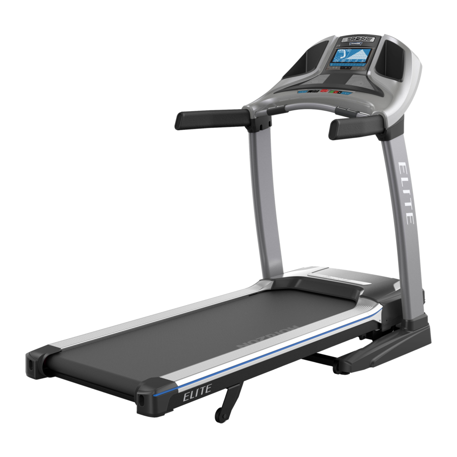
Horizon Fitness ELITE T7, T9 - Treadmill Manual
- Operation manual (33 pages) ,
- Assembly manual (23 pages) ,
- Operation manual (56 pages)
Advertisement
ASSEMBLY

There are several areas during the assembly process that special attention must be paid. It is very important to follow the assembly instructions correctly and to make sure all parts are firmly tightened. If the assembly instructions are not followed correctly, the treadmill could have parts that are not tightened and will seem loose and may cause irritating noises. To prevent damage to the treadmill, the assembly instructions must be reviewed and corrective actions should be taken.
Before proceeding, find your treadmill's serial number located on a white barcode sticker near the on/off power switch and power cord and write it down.

SERIAL NUMBER LOCATION
PARTS AND FEATURES

TOOLS REQUIRED
- T-Wrench F
- L-Wrench
- Phillips Screwdriver (not included)
PARTS INCLUDED
- 1 Main Frame
- 2 Console Masts
- 1 Console
- 2 Water Bottle Holders
- 2 Handlebars
- 2 Main Frame Covers
- 2 Console Mast Covers
- 1 Polar® Chest Strap
- 1 Hardware Kit
- 1 Safety Key
- 1 Power Cord
- 1 Audio Adapter Cable
NEED HELP
![]() If you have questions or if there are any missing parts, contact Customer Tech Support.
If you have questions or if there are any missing parts, contact Customer Tech Support.
Contact information is located on the back cover of this manual.
PRE ASSEMBLY
UNPACKING
Place the treadmill carton on a level flat surface. It is recommended that you place a protective covering on your floor. Take CAUTION when handling and transporting this unit. Never open box when it is on its side. Once the banding straps have been removed, do not lift or transport this unit unless it is fully assembled and in the upright folded position, with the lock latch secure. Unpack and assemble the unit where it will be used. The enclosed treadmill is equipped with high-pressure shocks and may spring open if mishandled. Never grab hold of any portion of the incline frame and attempt to lift or move the treadmill.
- DO NOT ATTEMPT TO LIFT THE TREADMILL! Do not move or lift treadmill from packaging until specified to do so in the assembly instructions. You may remove the plastic wrap from console masts.
- FAILURE TO FOLLOW THESE INSTRUCTIONS COULD RESULT IN INJURY!
IMPORTANT NOTES
 During each assembly step, ensure that ALL nuts and bolts are in place and partially threaded. It is recommended you complete the full assembly of your unit before completely tightening any ONE bolt.
Several parts have been pre-lubricated to aid in assembly and usage. Please do not wipe this off. If you have difficulty, a light application of lithium bike grease is recommended.
ASSEMBLY STEP 1

HARDWARE FOR STEP 1
| PART | TYPE | QTY |
| A | HEX SOCKET BOLT | 2 |
- Cut the yellow banding straps and lift the running deck upward to remove all contents from underneath the running deck.
- Open hardware for STEP 1.
- Insert 2 BOLTS (A) into MAIN FRAME (1).
ASSEMBLY STEP 2

HARDWARE FOR STEP 2
| PART | TYPE | QTY |
| B | BUTTON HEAD BOLT | 4 |
| C | SPRING WASHER | 4 |
| D | FLAT WASHER | 4 |
NOTE: Do not fully tighten bolts until step 6.
- Open HARDWARE FOR STEP 2.
- Attach LEFT CONSOLE MAST (2) to MAIN FRAME (1) using 4 BOLTS (B), 4 SPRING WASHERS (C) and 4 FLAT WASHERS (D).
ASSEMBLY STEP 3

HARDWARE FOR STEP 3
| PART | TYPE | QTY |
| B | BUTTON HEAD BOLT | 4 |
| C | SPRING WASHER | 4 |
| D | FLAT WASHER | 4 |
NOTE: Do not fully tighten bolts until step 6.
NOTE: Be careful not to pinch the console cable while attaching the right console mast.
- Pull the CONSOLE CABLE (3) away from the treadmill base frame. Connect the CONSOLE CABLE (3) from the MAIN FRAME (1) to the CONSOLE CABLE (3) in the bottom of the RIGHT CONSOLE MAST (4). The other end of the CONSOLE CABLE should be located at the top of the mast.
- Open HARDWARE FOR STEP 3.
- Attach RIGHT CONSOLE MAST (4) to MAIN FRAME (1) using 4 BOLTS (B), 4 SPRING WASHERS (C) and 4 FLAT WASHERS (D).
ASSEMBLY STEP 4

NO HARDWARE FOR STEP 4
- T7 models only: Slide MAIN FRAME COVERS (5) over CONSOLE MASTS (4).
- All models: Slide CONSOLE MAST COVERS (6) over CONSOLE MASTS (4).
ASSEMBLY STEP 5

HARDWARE FOR STEP 5
| PART | TYPE | QTY |
| E | BUTTON HEAD BOLT | 6 |
| C | SPRING WASHER | 6 |
| D | FLAT WASHER | 4 |
| F | ARC WASHER | 2 |
NOTE: Do not fully tighten bolts until step 6.
- Open HARDWARE FOR STEP 5.
- Place RIGHT HANDLEBAR (7) into top of RIGHT CONSOLE MAST (4).
- Insert 1 BOLT (E), 1 SPRING WASHER (C) and 1 FLAT WASHER (D) from the front-facing side of the CONSOLE MAST (4).
- Insert 1 BOLT (E), 1 SPRING WASHER (C) and 1 FLAT WASHER (D) from the insidefacing side of the CONSOLE MAST (4).
- Insert 1 BOLT (E), 1 SPRING WASHER (C) and 1 ARC WASHER (F) from the rear-facing side of the CONSOLE MAST (4).
- Repeat steps B–E on other side.
ASSEMBLY STEP 6

HARDWARE FOR STEP 6
| PART | TYPE | QTY |
| G | BUTTON HEAD BOLT | 4 |
| C | SPRING WASHER | 4 |
| D | FLAT WASHER | 4 |
NOTE: Be careful not to pinch the console cables while attaching the console.
- Open HARDWARE FOR STEP 6.
- Gently place CONSOLE (8) on top of CONSOLE MASTS (2 & 4).
- Connect the CONSOLE CABLES (3) and ensure cables are inside the right CONSOLE MAST (4).
- Connect the CONSOLE (8) to the right CONSOLE MAST (4) using 2 BOLTS (G), 2 SPRING WASHERS (C) and 2 FLAT WASHERS (D).
- Repeat STEP D on left side.
ASSEMBLY STEP 7

HARDWARE FOR STEP 7
| PART | TYPE | QTY |
| H | SCREW | 4 |
| I | SCREW | 2 |
- Open HARDWARE FOR STEP 7.
- Slide CONSOLE MAST COVERS (6) up and attach to masts using 4 SCREWS (H).
- Insert CONSOLE POCKETS (9) into CONSOLE (8) and attach using 2 SCREWS (I).
T7 ASSEMBLY COMPLETE!
ASSEMBLY STEP 8 (T9 ONLY)
")
HARDWARE FOR STEP 8
| PART | TYPE | QTY |
| H | SCREW | 6 |
*This step is for T9 models only.
- Fold the deck into the upright position until the FOOT LATCH (10) engages.
- Open HARDWARE FOR STEP 8.
- Silde the MAIN FRAME COVERS (5) down over the MAIN FRAME (1). The notches on the inside of the covers should align with the SPACERS (11).
- Attach MAIN FRAME COVERS (5) to MAIN FRAME (1) using 4 SCREWS (H).
- While holding the deck with both hands, press the FOOT LATCH (10) with your foot to lower the deck to the ground.
T9 ASSEMBLY COMPLETE!
Documents / ResourcesDownload manual
Here you can download full pdf version of manual, it may contain additional safety instructions, warranty information, FCC rules, etc.
Advertisement


Need help?
Do you have a question about the ELITE T7 and is the answer not in the manual?
Questions and answers