
Subscribe to Our Youtube Channel
Related Manuals for SEFRAM SPT50


Summary of Contents for SEFRAM SPT50
- Page 1 DUST EMISSION CONTROLLER 11bis, PLACE GUTENBERG - 59175 TEMPLEMARS (France) Tel: +33(0)3 20 60 49 49 - Fax: +33(0)3 20 95 59 62 Email: contact@sefram.eu Web: www.sefram.eu Technical manual FI 72.0574.0224E Page 1 / 15...
-
Page 2: Table Of Contents
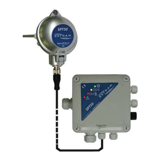
CONTROLLER SOMMAIRE : DESCRIPTION : Page The SPT50 is a dust emission controller based on the principle of triboelectricity. It consists of two parts: - DESCRIPTION - a sensor directly installed on the duct or conduit to be monitored. The sensor probe is immersed in the particle-laden air flow. It - CHARACTERISTICS evaluates the dust emission rate in real time. -
Page 3: Characteristics
Current consumption (rated current): 42mA - Protections : By self-resetting fuse - Operating temperature : Outside the pipe, body of the SPT50 sensor : -20° to 60°C Part inside the duct : flow <150°C (standard SPT 50 sensor) - Storage temperature : -20°... -
Page 4: Assembly, Dimensions And
DUST EMISSION CONTROLLER ASSEMBLY, DIMENSIONS AND FIXING: Sensor : The sensor is fixed directly to the duct to be monitored under the following conditions: - G1/2" thread - Placed in a straight section as shown in the diagram below, - On an earthed metal sheath, earth continuity must be ensured between the probe and the sheath section. Connect the probe to earth via the terminal on the body of the probe. - Page 5 DUST EMISSION CONTROLLER Cover locking screw Sensor head M20 gland Stainless steel locknut Cylindrical thread G1/2 Stainless steel link PTFE insulator 3 fixing screws of the rod ATEX version Technical manual FI 72.0574.0224E Page 5 / 15...
-
Page 6: Connection Box
DUST EMISSION CONTROLLER Connection box (base): ISO16b : power supply ISO16b : relay outputs ISO12 : sensor connection ISO12 : 4-20mA output Gland clamping capacity : M12-4PTS connector For control console connection ISO 12 De 3 to 6 mm Or USB/PC cable for adjustment ISO 16b De 5 to 10 mm 6, 7... - Page 7 DUST EMISSION CONTROLLER Fixings : either fixing from the rear of the case : 4 fasteners for 4mm diameter screws Back view either front fixing using a kit : 4 fastenings Assembly kit : Front view Technical manual FI 72.0574.0224E Page 7 / 15...
-
Page 8: Connections
The cable conductors must be flexible and have a cross-section of between 0.25 and 1.5 mm2. BASE : Please note: No sensor other than the SPT50 may be connected to the base, as this could damage the product. Power supply 24VDC : Communication connections 24VDC =>... - Page 9 Shield connected to EARTH at both ends of cable Input/Output communication 2x0.25² shielded interlaced Shield connected to EARTH at both ends of cable SPT50 sensor 4x0.5² shielded Shield connected to EARTH on BASE side Connection CAPTEUR <> BASE: View of the sensor board:...
-
Page 10: Adjustment / Calibration
DUST EMISSION CONTROLLER ADJUSTMENTS / CALIBRATION: The SPT50 is set up by connecting a control console or PC to the M12 connector on the right-hand side of the SPT50 base. SPT50 M12 connector: M12 connector pins signal number 24VDC RS485/A RS485/B See related documentation. -
Page 11: Modbus Communication
Several SPT50 can be connected to the same Modbus network using an adjustable identifier. The SPT50 are then wired in series on the Modbus network. For wiring, the connection box has 2 glands (1 for the cable coming from the previous box and another for the cable going to the next box). - Page 12 DUST EMISSION CONTROLLER Modbus exchange table: Adr. Mod- Mod- word word Content HEXA- DECI- DECI- Not used Flags operation Bit0 : =1 if rejection alarm (average rejection over x minutes>alarm threshold) Bit1 : =1 if reject alert (average reject over x minutes>threshold alert) Bit2 : =1 if high temperature alarm Bit3 : - reserved - Bit4 : - reserved -...
-
Page 13: Signals
DUST EMISSION CONTROLLER SIGNALS : Green LED : Flashes if in operation Orange LED : Steady light for rejection alert Red LED : Steady light for rejection alarm Red LED : Off in normal operation Permanently lit if there is no communication with the sensor Flashing code according to problem : 2 times: temperature alarm 3 times: electronic problem (from sensor) -
Page 14: Precautions
- When used outdoors, the device is not designed for direct exposure to rain or sunlight. It is recommended that a protective cap be fitted to the top of the device. - Cables connected to the SPT50 dust emission controller should, as far as possible, be routed close to a metal structure. -
Page 15: General Safety, Assembly
Before any intervention on the cabinet, the equipment must be In the event of a problem, please contact Sefram. de-energized by cutting off the power source upstream of it. V. MAINTENANCE II.
Need help?
Do you have a question about the SPT50 and is the answer not in the manual?
Questions and answers