
Related Manuals for SEFRAM SPX50


Summary of Contents for SEFRAM SPX50
- Page 1 DUST EMISSIONS CONTROLLER SEFRAM PLACE GUTENBERG 59175 TEMPLEMARS (France) Tel: +33(0)3 20 60 49 49 - Fax: +33(0)3 20 95 59 62 Email: contact@sefram.eu Web: www.sefram.eu FI 72.0066.1018E Notice Technique Page 1 sur 17...
-
Page 2: General Details
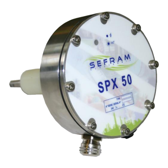
GENERAL DETAILS The SPX 50 is a dust emissions controller which uses the principle of triboelectricity. It is fitted directly into the duct or pipe to be monitored with the SPX 50 sensor being inserted into the particle-filled air flow. The SPX 50 is available in three versions: - alarm version with transfer to relay inverter contact, - 4-20 mA transmitter version,... -
Page 3: Mechanical Assembly
MECHANICAL ASSEMBLY The sensor is fitted directly to the duct to be monitored under the following conditions: - 1" / 26-34 mm thread (BSP or pipe thread), - positioned in a straight portion in line with the following diagram, - on a metal duct connected to earth, the continuity of the earth between the sensor and the duct section must be ensured, - sensor length (100 - 500 mm) to be suited to the duct (e.g. -
Page 4: Mechanical Dimensions
MECHANICAL DIMENSIONS NEWCAP-MS M16 N°6 Mini 4,5mm Maxi 10mm FI 72.0066.1018E Notice Technique Page 4 sur 17... -
Page 5: Electrical Connections
ELECTRICAL CONNECTIONS The connection terminals can be accessed after removing the cover. The connections are made using a cable with at least 4 conductors. Maximum conductor cross section: 0.5 mm². Recommended cable: HI FLEX-CY 4x0.5². It is recommended that a voltage 24 V AC is used for the alarm contacts. - Page 6 4-20 mA transmitter version: The 4-20 mA is of active integrated 24 V DC voltage type. FI 72.0066.1018E Notice Technique Page 6 sur 17...
- Page 7 - In the network version, the "alarm" output to relay function is maintained. The interface unit incorporates the interface relays for using contacts up to 2.5 A 250V AC1. - Dialogue connections are of RS485 type using the secure SEFRAM protocol. The network:...
- Page 8 Sensor connection: Sensor encoding: FI 72.0066.1018E Notice Technique Page 8 sur 17...
- Page 9 The SPX 50 RS-BR interface unit: The SPX 50 RS-BR interface unit is used to connect the sensors of the network to the PC. It includes the SPX 50 alarm relay interfaces. Main specifications: - Main supply: 230V 50 Hz - Power consumption: 40 VA - Fuse protection F1 F2 general 500 mA protection (250V)
- Page 10 FI 72.0066.1018E Notice Technique Page 10 sur 17...
- Page 11 Dialogue connection with the interface unit: - Connect all terminals "A" together and all terminals "B" together. FI 72.0066.1018E Notice Technique Page 11 sur 17...
- Page 12 THE UNIT FI 72.0066.1018E Notice Technique Page 12 sur 17...
-
Page 13: Specifications
SPECIFICATIONS Power supply 24V AC or DC Power consumption < 100 mA Alarm relay 1A 24V AC/DC inverter contact active, max load 500 Ω 4-20 mA Network RS 485 type. Max length < 1.2 km (depending on cable) Parameter settings using pocket unit or PC 1 LED on front panel →... - Page 14 ADJUSTMENTS Regardless of the version, the SPX 50 is adjusted in the same way using the pocket unit or a PC. 3 automatic functions are available to the operator: 1) Auto sensitivity: During installation, the unit must be calibrated in relation to the environment into which it is installed (installation type, dust, concentration, etc.).
-
Page 15: Operation
OPERATION Alarm version: The SPX 50 calculates an average value as a function of the duration set by the user. If the average value exceeds the alarm reference limit, the alarm relay "falls" and the LED on the front of the unit flashes. - Page 16 RECEPTION - STORAGE In the event of a problem, please contact Sefram. After unpacking the device, check that this latter has not MAINTENANCE been damaged during transport; for certain devices, The device does not require any special maintenance.
-
Page 17: Maintenance
59175 TEMPLEMARS FRANCE CERTIFICATE The SPX50 respects the European directives ( CEM and ATEX ), which concerns it. However, it must be used correctly in applications for which it is intended, and should be linked or near CE approved products.
Need help?
Do you have a question about the SPX50 and is the answer not in the manual?
Questions and answers