Table of Contents
Advertisement
Quick Links
TECHNICAL NOTICE
2006 SEFRAM
All rights reserved. Made in France.
Technical Data Sheet
SEQUENCER CONTROLLER
SFX+ NETWORK
PLACE GUTENBERG - 59175 TEMPLEMARS (France)
Tel: +33(0)3 20 60 49 49 - Fax: +33(0)3 20 95 59 62
Email:
contact@sefram.eu
ELECTRONICS DEDICATED TO DEDUSTING
AND AIR QUALITY
FI 72.0239.0320E
Web:
www.sefram.eu
Page 1 / 108
Advertisement
Table of Contents

Related Manuals for SEFRAM SFX+NETWORK


Summary of Contents for SEFRAM SFX+NETWORK
- Page 1 SEQUENCER CONTROLLER SFX+ NETWORK TECHNICAL NOTICE 2006 SEFRAM All rights reserved. Made in France. PLACE GUTENBERG - 59175 TEMPLEMARS (France) Tel: +33(0)3 20 60 49 49 - Fax: +33(0)3 20 95 59 62 Email: contact@sefram.eu Web: www.sefram.eu ELECTRONICS DEDICATED TO DEDUSTING...
-
Page 2: Table Of Contents
CONTENTS I – GENERAL DETAILS (page 4) II – GENERAL SPECIFICATIONS MAIN BOX (page 6) III – CONSTITUTION OF THE SFX+ NETWORK (page 7) IV – CU CARD (page 8) V – THE VARIOUS PLUG-IN MODULES (page 14) - COMMON CHARACTERISTICS (page 14) - POWER MODULE (page 17) - MODULE: 4 AON INPUTS... - Page 3 - THE VISU MENU (page 70) - CYCLE (page 71) - A/C MEASURES (page 72) - FAULTS (page 73) - COUNTS (page 74) - IINFOS (page 74) - HISTORICAL (page 75) - THE MANU MENU (page 78) - MANUAL RUNNING (page 78) - DURING X CYCLES (page 79) - OUTPUT FORCING (page 80) - CYCLE POSITION...
-
Page 4: I - General Details
I - GENERAL DETAILS The SFX+ NETWORK is a compact and modular sequencer dedicated to dust removal and checking and monitoring the filtration / dust removal process. The modular design of its hardware and software means that it can be configured rationally to fulfil the most diverse applications. - Page 5 Main box: Up to 99 Slave boxes: A box consists of up to 18 solenoid valve (EV) outputs with or without: - mini pilot - compressed air pressure switch (Pressostat) - cell/tank isolation management - cell position control 1 MDPP2000 box: Pressure switch Loss of load Printer...
-
Page 6: General Specifications Main Box
II – GENERAL SPECIFICATIONS MAIN BOX Customer power supply According configuration 24/48V or 115/230V AC 50/60 Hz Insulation through internal transformer 24/48V DC Isolated DC/DC converter recommended General protection By 5x20 fuse on the power supply module and on the filter module Output protection Individual by 5x20 fuse on the modules Operating temperature... -
Page 7: Constitution Of The Sfx+ Network
III – CONSTITUTION OF THE SFX+ NETWORK Main box SFX+ NETWORK must comprised: 1 CU card (Central Processing Unit) 1 power supply module 2 filter modules The following modules can be added to this main box to form the required sequencer. - Module with 8 AC outputs (triacs) - Module with 8 DC outputs (transistors) - Module with 8 relay outputs... -
Page 8: Cu Card
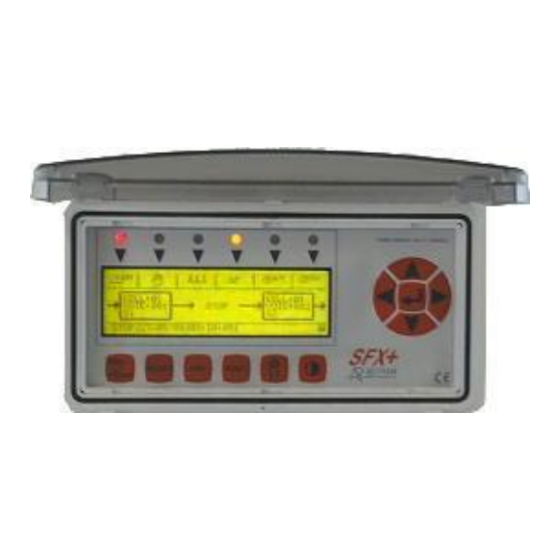
IV – CU CARD The CU card (Central Unit) controls all of the modules, slaves and outside communication. It acts as the SFX+ / user interface via its front panel. CHARACTERISTICS Consumption 0.9A under 5V Calendar 11 years retention (de-energized) Precision +/- minute per month maximum. - Page 9 THE NAVIGATOR The buttons on the navigator are used to move within the menus, to adjust parameters and to validate data. Up / + Right Left Valid Down / - THE BUTTONS RUN / STOP button: - RUN: SFX+ operation authorisation - STOP: stop dust removal.
- Page 10 GRAPHICAL DISPLAY / SIGNALLING LEDS The graphical display is of STN LCD type with LED backlighting. The contrast is adjusted automatically as a function of usage temperature. By defect, the display shows: Technical Data Sheet FI 72.0239.0320E Page 10 / 108...
- Page 11 4 pin connector (for link type RS485/RS422) o cabling on one OR other COM4: reserved for the link to SEFRAM devices (slaves boxes / MDPP2000) o 4 pin connector (for link type RS422) visu of the inside of the cabinet /main box, back of the UC: Technical Data Sheet FI 72.0239.0320E...
- Page 12 Remark: When you are in the display by defect, the RIGHT navigator button allows the activity on the communication ports to be displayed. The corresponding LEDs light up each time information is received: Example of a MDPP2000 and several slave boxes connection: Remarks: - the last box placed on the bus must be equipped with a load (the load is plugged in to the coupling connector)
- Page 13 Cabling between CU card and a PC: BATTERY REPLACEMENT All of the settings/parameters and the history record are stored in memories safeguarded by two batteries of type R6. Remove the central unit protection lid to gain access to these. TAKE CARE WITH THE DIRECTION BATTERY R6 TYPE The batteries enable the data to be retained for an estimated period of two years if the central unit card is not powered (the period can vary depending on the power of the batteries used: calculated with 1.5Ah...
-
Page 14: Common Characteristics
V – DIFFERENTS PLUG-IN MODULES COMMON CHARACTERISTICS Apart from the filter module mounted directly on the back panel, all the other modules can be plugged onto the 35 mm symmetrical DIN rail. ACCESS TO THE CONNECTIONS The connection terminals are accessed by opening the door of the module. A connection label specific to each type of module is affixed to the back of the door. - Page 15 ASSEMBLY: 1) Whilst holding the module, Position the fixed slot of the module on the upper edge of the rail 2) Pivot the module downwards, holding it against the rail. 3) Reconnect the jumper A and the connection terminals Technical Data Sheet FI 72.0239.0320E Page 15 / 108...
- Page 16 REMOVING THE DOOR With the door open, press slightly on the bottom of the module. Release the door starting with the lower hinge pin. REFITTING THE DOOR Release the bottom of the module by pressing slightly and insert the top pin then the bottom pin. ACCESS TO THE FUSES All the outputs are individually protected by 5x20 fuses.
-
Page 17: Power Module
POWER MODULE MAIN SPECIFICATIONS Module reference: SFX+ ALIM Module supply: 24V 50/60 Hz Or 24V DC Supply to the relays, input, outputs and modules via the power module. Input: 24V 50/60 Hz 24V DC The power module supplies all of the modules with +5V Fan-out of the +5V: 2 A Protection: by 5x20 fuse on the module supply and input and relay output supply. - Page 18 CONNECTIONS TO CU MODULE SUPPLY AND INTERNAL BUS INTERNAL 5V TRANSFER FOR START OF LINE SUPPLY 24V 50/60Hz OR 24V DC MODULE SUPPLY OUTPUT 24V DC FOR SUPPLY TO INPUTS AND RELAY MODULES INPUT 24V 50/60Hz OR 24V DC FOR SUPPLY TO INPUTS AND RELAY MODULES Technical Data Sheet FI 72.0239.0320E...
- Page 19 FUSES LOCATIONS F1, F2: supply protection fuses Module size 5x20 glass, rating 1A type F F3, F4: supply protection fuses of the input and relay output modules Size 5x20 glass, rating 1A type F Technical Data Sheet FI 72.0239.0320E Page 19 / 108...
- Page 20 - Input impedance: 2.7 K - Input seen at 1 at U 13.5V I = 4.5 mA at 13.5V - Response time: configurable from 1/100 - 255/100 seconds (SEFRAM adjustment) - Input type: resistive - 2 and 3 wire proximity detector compatibility: yes (contact us)
- Page 21 SIGNALLING Technical Data Sheet FI 72.0239.0320E Page 21 / 108...
- Page 22 CONNECTIONS CONNECTION EXAMPLE Technical Data Sheet FI 72.0239.0320E Page 22 / 108...
-
Page 23: Aon Inputs Module
- Input impedance: 2.7 K - Input seen at 1 at U 13.5V I = 4.5 mA at 13.5V - Response time: configurable from 1/100 - 255/100 seconds (SEFRAM / factory adjustment) - Input type: resistive - 2 and 3 wire proximity detector compatibility: yes (contact us) - Page 24 CONNECTIONS CONNECTION EXAMPLE Technical Data Sheet FI 72.0239.0320E Page 24 / 108...
-
Page 25: Relay Outputs Module
8 RELAY OUTPUTS MODULE MAIN SPECIFICATIONS Module reference: SFX+ SRL - N° of outputs per module: 8 - Max operating voltage: 250V AC - Nominal current: 4A AC1 (per way) - nominal cut-off power (ohmic load): 2000VA - Max load for direct current: ohmic load 4A 38V 1.5A 48V DC inductive load 0.4A 34V 0.2A 48V (L/R = 20 ms) - Response time: make / break: 10 ms - Type of contact: closing... - Page 26 CONNECTIONS CONNECTION EXAMPLE Technical Data Sheet FI 72.0239.0320E Page 26 / 108...
-
Page 27: Ac Outputs Module
8 AC OUTPUTS MODULE MAIN SPECIFICATIONS Module reference: SFX+SAC1C → with 1 "common" terminal for 8 solenoid valves SFX+SAC8C → with 8 "common" terminals for connection without common - N° of outputs per module: 8 - Type of outputs: TRIAC - Max operating voltage: 24V AC →... - Page 28 CONNECTIONS CONNECTION EXAMPLE Technical Data Sheet FI 72.0239.0320E Page 28 / 108...
- Page 29 FUSES LOCATIONS Fuses FS1 - FS8 are glass 5x20 fuses, 250 V max to be calibrated depending on max load: 2.5A fusion type F. Technical Data Sheet FI 72.0239.0320E Page 29 / 108...
-
Page 30: Dc Outputs Module
8 DC OUTPUTS MODULE MAIN SPECIFICATIONS Module reference: 24V DC outputs: SFX+SDC1C24/SFX+SDC8C24 48V DC outputs: SFX+SDC1C48/SFX+SDC8C48 - N° of outputs per module: 8 - Type of outputs: transistor - Max operating voltage: SFX+SDCXC24: 30V DC SFX+SDCXC48: 60V DC - Allowable currents on the outputs: total for 1 module: 3A on 1 way one-touch: 2.5 A max / permanent: 1A - Voltage drop on 1 way: with fault control +/- 4V at 2.5A... - Page 31 CONNECTIONS CONNECTION EXAMPLE Technical Data Sheet FI 72.0239.0320E Page 31 / 108...
- Page 32 FUSES LOCATIONS Fuses FS1 - FS8 are glass 5x20 fuses with rating depending on max load (max 2.5 A) fusion type F. Technical Data Sheet FI 72.0239.0320E Page 32 / 108...
-
Page 33: Transfer Module
TRANSFER MODULE MAIN SPECIFICATIONS The transfer module is a communications and signal conversion module. It is used: - to act as a secure module line transfer with an END of line module and a START of line module (RS485) Module reference: - end of line module: SFX+ RPTF - start of line module: SFX+RPTD - 485 transfer module: SFX+RPT485 SIGNALLING... - Page 34 CONNECTIONS Technical Data Sheet FI 72.0239.0320E Page 34 / 108...
- Page 35 POSITION SWITCHES This module has switches which can be accessed on the side of the module: Technical Data Sheet FI 72.0239.0320E Page 35 / 108...
-
Page 36: Filter Module
FILTER MODULE The module filters the main power supply and it is ESSENTIAL to connect the earth conductor of the protections directly to the filter module with a CROSS SECTION of 2.5 mm² Operating voltage: 250V 50-60 Hz Max nominal current: 3.4 A at 25° C Leakage current: 2x0.21 mA FILTER WITHOUT COVER FILTER WITH COVER... -
Page 37: Sfx+ Module Power Consumption
SFX+ MODULE POWER CONSUMPTION Technical Data Sheet FI 72.0239.0320E Page 37 / 108... - Page 38 Technical Data Sheet FI 72.0239.0320E Page 38 / 108...
- Page 39 VI – SLAVE BOXES Depending on the filter configuration, several slave boxes are used. The mains voltage, the output voltages, the slave box equipment, the coding of these and also the size of the casing depends on the specification. → SEE ATTACHED ANNEXE NOTICE Slave general characteristic: consumption: 8 VA + S.V.
- Page 40 The slave boxes are cabled on a secure bus. Each slave is numbered to define its function in the installation. This coding is produced by two coding wheels on the electronic card located S2 and S3. When there is any card change, this card must be coded before being connected to the bus. Classification from 1 to The last box on the bus S2 : ten...
- Page 41 VII – MDPP2000 BOX A pressure switch MDPP2000 (special version SFX+NETWORK) can be connected on the bus in order to obtain the information « loss of load ». The “ID” number of the MDPP2000 must be adjusted to “1” (see MDPP2000 notice).
-
Page 42: The Menus
VIII – THE MENUS The SFX+ uses 3 menus: - the "SELECT" menu for configuring the SFX+ - the "VISU" menu for the operation / status of the SFX+ - the "MANU" menu for forcing the SFX+ THE SELECT MENU PRESENTATION To activate the select menu, press the SELECT button and the menu below will appear. - Page 43 SFX+ CONFIGURATION / SETTINGS Use the navigator buttons in the "SELECT" menu, to access the settings of a parameter: - go to the parameter to be set using the buttons - Press the button - Adjust the parameter * by placing the cursor over the desired figure using the buttons * with the buttons, the number is incremented or decremented...
- Page 44 CODE After having placed the arrow on CODE and pressed . 2 displays may appear depending on the protection status (code already entered or not): - Protection activated (code not valid) Code entry range In this case, enter the code using the buttons then validate by pressing .
- Page 45 - Change the password If the arrow is placed on this step and if the button is pressed, the following sub-menu appears: New code entry range Set the new code required using the buttons and press the button. This operation will store the new code and will then return to the "SELECT"...
- Page 46 NUMBER OF WAYS If the arrow is placed on this step and if the button is pressed, the following sub-menu appears: Press to return to the "SELECT" menu. Remark: In a configuration where there is a number of different ways in the filter cells, the value stated is the way number of the largest cell.
-
Page 47: Adjusting The Times
ADJUSTING THE TIMES The principle for adjusting a time is the same for all of them. - If protection is active, the adjustment range xxx<X<xxx is replaced by "PROTECTED BY CODE". - The adjustment range depends on the time being adjusted. If the arrow is placed on a time and if the button is pressed, the following display appears: Possible adjustment range... - Page 48 Adjustable from 0 - 255 seconds. T8: MINI PRESSURE → Header inflation time before min pressure check. Adjustable from 1 - 255 seconds. T9 : SERVICE PRESSURE → Header reinflation TIMEOUT after pulse from 1 dust removal solenoid valve. Adjustable from 1 - 255 seconds. T10: POSITION CELL.
-
Page 49: Nb Cycles Stop Fan
NB CYCLES STOP FAN When the fan loop control input is lost, the SFX+ completes the current cycle and performs the number of dust removal cycles defined in this menu step independently to the operating orders (except A/C loop control). If the arrow is placed on NB CYCLES STOP FAN and the button is pressed, the following display appears. -
Page 50: Stop Type
STOP TYPE When the SFX+ loses the operating orders, the dust removal cycle has 2 stopping modes: - Stop “ON CYCLE” → the SFX+ stops the dust removal cycle as soon as the operating orders are lost. The cycle will restart from where it was when the operating orders are once again present. - Stop “END OF CYCLE”... -
Page 51: Nb Simultan. Pulses
NB SIMULTAN. PULSES In ONLINE dust removal, it can be interested to declog several “rows” simultaneously (1 to 16). If the arrow is placed on NB SIMULTAN.PULSES and if the button is pressed, the following display appears: Possible adjustment range Note: Protected by code! appears if protection is activated. - Page 52 3 SIMULTANEOUS SHOTS: Note: the T16 time value is adjustable (see T16 : SIMULTAN.PULSES) or fixed (fixed value at the programming). (T16 from 10 to 255 1/100 of second). As regards a configuration with slave boxes, the time T16 is reduced to the minimum and its value is that imposed by the link.
-
Page 53: Nb Step Online
NB STEP ONLINE It may be of interest within a dust removal process to perform several dust removal operations on the same "ramp" within the same cycle. By adjusting the number of ONLINE steps, one or several solenoid valves can be allocated to different pulse order numbers within the same cycle. -
Page 54: Online Cycle
ONLINE CYCLE This menu step is used to configure the dust removal order for one cycle for an ONLINE dust removal filter. Principle: a pulse order number is associated to a solenoid valve (or several SV in the case of simultaneous shots). - Page 55 Note: if running with simultaneous shots, display is: - If 2 simultaneous shots: - If 3 simultaneous shots: Important: in the event of simultaneous shots, and in a configuration with slave boxes, the simultaneous shot of several ways in the same cell is not prohibited by the setting. Take care not to choose several ways on the same box in the same step because, in this case, only the first way requested can be taken into account.
-
Page 56: Nb Step Offline-Way
NB STEP OFFLINE-WAY It may be of interest within an OFFLINE dust removal process to perform several dust removal operations on the same "ramp" within a cell. By adjusting the NB STEP OFFLINE-WAY, one or several dust removal solenoid valves can be allocated to different pulse order numbers. -
Page 57: Offline-Way Cycle
OFFLINE-WAY CYCLE This menu step is used to configure the dust removal order in a cell. It is the same for all cells in the filter. Principle: a pulse order number is associated to a dust removal solenoid valve. Dust removal in a cell starts on the pulse with order number 1 and ends on the pulse with order number = to the parameter NB STEP OFFLINE-WAY. -
Page 58: Nb Step Offline-Cell
NB STEP OFFLINE-CELL It may be of interest within an OFFLINE dust removal process to perform several dust removal operations on the same cell within a cycle. By adjusting the NB STEP OFFLINE-CELL, one or several cells can be allocated to different cell dust removal order numbers. -
Page 59: Offline-Cell Cycle
OFFLINE CYCLE - CELL This menu step is used to configure the dust removal order of the cells in a cycle. Principle: a cell in which dust removal is to be performed is associated to a cell cycle number. A dust removal cycle starts with the cell cycle number 1 and ends with the cell cycle number = to the NB STEP OFFLINE-CELL. -
Page 60: A/C Threshold
A/C THRESHOLD In the case of a configuration with slave boxes equipped with compressed air pressure sensors: this menu step allows the adjustment of the A/C mini header pressure threshold, the A/C operating pressure threshold, and the value of the fall pressure during a shot. If the arrow is placed on A/C THRESHOLD and if the button is pressed, the following display appears:... - Page 61 - A/C OPERATING PRESS. A/C operating pressure threshold allows controlling the headers pressure during the phase of dust removal in order to control the consumption during a shot and the re-inflation after the shot. This threshold is used to create header re-inflation faults and no consumption header (see re-inflation fault and Pressostatic filter cleaning solenoid valve not open fault).
-
Page 62: Dp Threshold
DP THRESHOLD In the case of a configuration with a MDPP2000 on the bus (with “ID” number to 1), This menu step permits the setting of the different thresholds on this (see MDPP2000 notice) If the arrow is placed on DP THREHOLDS and if the button is pressed, the following display appears: The four values adjustment is the same. -
Page 63: Date/Time
DATE / TIME The SFX+ controls the date and time for the log and for faults. To change the date and time: - Place the arrow on DATE / TIME and press the button and the following display appears: Remark : the display format is DD/MM/YY (day / month / year) HH :MN :SS (hour : minute : second) Note: Protected by code! appears if protection is activated. -
Page 64: Outputs Name
OUTPUTS NAMES A name can be assigned to each filter cleaning solenoid valve. These names are used for the cycle visualisation, the signalling/localisation of faults, etc. To allocate a name to an output: - Place the arrow on OUTPUT NAMES and press the button and the following display appears: selection rectangle... -
Page 65: Modbus Com
Press to save the parameters and return to the select menu. The SFX+ has the following MODBUS functions: 03h, 06h and 10h. See « Annexe MODBUS exchange table SFX+NETWORK» for the detail of the exchanged values. Technical Data Sheet FI 72.0239.0320E... -
Page 66: Pc Com
PC COM. It allows an identifier to be defined (1 to 32) through the remote connection (with PC soft) and to indicate the transmission speed (9600, 57600 or 115200 bauds). Notes: - The format is set at 8 data bits, 2 stop bits and no parity. - the identifier will be required to initialise the connection from the remote PC. -
Page 67: Nb.flt.dust. Emiss
NB.FLT.DUST. EMISS. This parameter is used in the case of a configuration with a dust emission control. It determines whether or not the filter cleaning on the solenoid valves which have presented a dust emission fault should be continued (see dust emission faults). Place the arrow on NB.FLT.DUST.EMISS. -
Page 68: Config. Save
CONFIG. SAVE This menu step allows make a security backup of the settings/parameters of the SFX+ NETWORK so that they can be recovered, for example, if there is a manipulation error, change batteries, etc. Place the arrow on CONFIG. SAVE and press the button. -
Page 69: Open/Close Control
OPEN/CLOSE CONTROL This parameter is used in the case of a configuration with a control of opened/closed cells. Choice whether or not the positioning control cells should be performed. If choice « YES » : the positioning inputs « opened cell » and « closed cell » are checked. If choice «... - Page 70 VISU MENU PRESENTATION The visu menu is used to display the status of the dust removal cycle, faults, historical and various information. The « visu cycle » display is a priority and automatic if no buttons on the front panel are pressed for more than 60 seconds.
- Page 71 CYCLE Cycle visu is used to view the status of the dust removal cycle and the basic information. If the arrow is placed on CYCLE and if the button is pressed, the following display appears: Technical Data Sheet FI 72.0239.0320E Page 71 / 108...
- Page 72 A/C MEASURES This menu step is available in the case of a configuration with slave boxes equipped with pressure sensor. It allows to view the pressures measured at the compressed air headers and the mini pressure OK status and service pressure OK of these. - If, the arrow is placed on A/C MEASURE and if the ...
- Page 73 FAULTS This menu step allows to view the possible faults present on the SFX+ NETWORK. According to the SFX+ configurations, several faults type can be handled. → see « faults control » chapter. To view faults: - If, the arrow is placed on FAULTS and if the button is pressed, the following display appears: - If no fault is memorised: - If memorised fault: To view the sequence of faults, use the...
- Page 74 COUNTERS The SFX+ controls various counters. To view the counters: If the arrow is placed on COUNTERS and if the button is pressed, the following display appears: The counters are shown on 2 pages: switch from one page to the next using the buttons.
- Page 75 HISTORICAL The SFX+ controls a log which has a recording capacity of 4096 events. The memory is of the « turning » type, therefore once it is full and a new event arrives, the oldest event is lost. Each event is dated. This menu step displays the list of the events recorded in the log If the arrow is placed on HISTORICAL and if the ...
- Page 76 - Put power on: At each put power on of the central unit card: « PUT POWER ON » - Put power off: At each voltage cut off of the central unit card: « PUT POWER DOWN » - Historical reset: At each historical memory reset: «...
- Page 77 At each appearance of a short-circuit on slave box electric fault: « FLT.S-C SLAVE:xx » with xx = slave box Number - SV dust emission faults: At each appearance of a SV dust emission fault: « DUST EMISSION:xx/yy » with xx = cell Number and yy = cell way Number - general dust emission fault: At each appearance of the general dust emission fault:...
- Page 78 THE MANU MENU PRESENTATION The SFX+ controls 4 manual operating modes. To activate the manual menu, press the MAN button and the following menu appears. Depending on the configuration of the SFX+, the steps in the menus which are shaded may or may not be available to the user.
- Page 79 DURING X CYCLES Manual operating mode is used to perform X cycles independently to operating orders. Once the X cycles are complete, the SFX+ returns to normal operating conditions. If the arrow is placed on DURING X CYCLES and if the button is pressed, the following display appears: - Adjust the number of cycles to be performed using the buttons.
- Page 80 OUTPUT FORCING Manual operating mode is used to force a declogging SV output (independently to the other procedures). If the arrow is placed on Output forcing and if the button is pressed, the following display appears: Position the selection rectangle on CELL with the buttons and choose the cell number with buttons Position the selection rectangle on WAY with the...
- Page 81 CYCLE POSITION The "CYCLE POSITION" from MANU menu allows to put the dust removal cycle to a shot number of the ONLINE cycle (only available if ONLINE running). If, arrow placed on "CYCLE POSITION", the button pressed, the following dispay appears: - Enter the shot number of the ONLINE cycle with buttons - Press ...
- Page 82 IX OPERATION GENERAL DETAILS Depending on the design of the filter and the process, the SFX+ NETWORK can control several operating cycles: - ON LINE dust removal cycle - OFF LINE dust removal cycle - PUT ON SERVICE cycle In the standard version, ON LINE or OFF LINE dust removal cycles are managed. The operating responses, the operating statuses, etc which may be given by the SFX+ are shown and detailed in the wiring diagrams.
- Page 83 ON LINE - The condition ON LINE = 1 if the ON LINE input is not controlled. - For manual operating conditions, see the MANUAL menu. Technical Data Sheet FI 72.0239.0320E Page 83 / 108...
- Page 84 OFF LINE - The condition OFF LINE = 1 if the OFF LINE input is not controlled. - For manual operating conditions, see the MANUAL menu. Technical Data Sheet FI 72.0239.0320E Page 84 / 108...
- Page 85 Technical Data Sheet FI 72.0239.0320E Page 85 / 108...
- Page 86 PUT ON SERVICE Aim: To prepare the filter → opens all the cells authorises header inflation. Switching on (=put on service) requests that the headers are inflated to open the header valves. Switching on (=put on service) is effective after inflating all the headers (service pressure reached) or after a timeout If at the end of switching on (=put on service), a header is not at its service pressure, but has reached the minimum, no faults are generated.
- Page 87 X - FAULT CONTROLS GENERAL DETAILS The SFX+ can manage the following fault controls: - Electrical fault - dust removal solenoid valve cut off - dust removal solenoid valve permanently passing (1 per module) - dust removal solenoid valve permanently passing (1 per slave box) - Cell opening fault - Cell closing fault - Mini pressure fault...
- Page 88 ELECTRICAL FAULT CONTROLS 2 types of electrical fault controls are managed by the SFX+. - The dust removal solenoid valve cut off electrical fault: In this case, when there is a pulse on a solenoid valve, the SFX+ NETWORK checks that a current does pass into the solenoid valve - output circuit.
- Page 89 - The permanent consumption electrical fault: In this case, the SFX+ NETWORK checks that no current is flowing in the outputs - solenoid valve when there is no pulse on the solenoid valves. If there is current consumption, the SFX+ NETWORK generates a short circuit electrical fault. The location can only be given at module or slave box level as the outputs of the same module or of the same slave box all have the same current control.
- Page 90 CELL OPENING / CLOSING FAULT CONTROL The SFX+ NETWORK can control opening or closing faults of the cells of a filter. It receives cell position information via its inputs through limit sensors. The position of the cells is determined by the SFX+ NETWORK.
- Page 91 MINI PRESSURE FAULT The compressed air headers associated to the cells forming the filter are each fitted with a pressostat and an isolation valve on the compressed air inlet. A min pressure level is permanently checked by the SFX+. If the compressed air pressure falls below this limit, the SFX+ generates a min pressure fault and isolates the header by controlling the isolation valve.
- Page 92 DUST REMOVAL SOLENOID VALVE NOT OPEN PRESSOSTATIC FAULT The compressed air headers associated to the cells forming the filter are link to a pressure sensor. This is capable of detecting a pressure drop in the headers when a pulse is given on one of its dust removal solenoid valves.
- Page 93 REINFLATION FAULT The compressed air headers associated to the cells forming the filter are each fitted with a differential pressure switch and an isolation valve on the compressed air inlet. The differential pressure switch measures a pressure limit adjusted for optimised dust removal. This limit must be reached to control the pulses on the dust removal solenoid valves.
- Page 94 DUST EMISSION FAULT Depending on the configuration, a dust emission check can be carried out. This involves: - checking that there is no appearance of a dust emission downstream during a shot on a filter cleaning solenoid. - checking that there is no appearance of a dust emission outside of a cleaning cycle This check is carried out from a logical input “dust emission”...
- Page 95 Checking outside of a cleaning cycle: Outside a cleaning cycle, the input “dust emission” is monitored. If a dust emission is detected, a “general dust emission” is generated. Notes: The dust emission detection is temporized (value of T19 time to adjust from 0 to 255 seconds in the SELECT menu).
- Page 96 DIALOG. FAULT This type of fault appears when becomes a dialogue problem between: The central unit card and a module The central unit card and a slave box The central unit card and a MDPP2000 The link faults are reported in the fault visualisation mode. A display bringing together all the link faults present (up to 8 of each type) is placed in the last position of the fault stack: in the above display example: - link fault on the modules n°20, 21 and 23...
- Page 97 XI - GENERAL INSTRUCTIONS FOR THE USER - The electrical installation upstream of the SFX+ equipment must comply with the provisions of power surge 2. - SFX+ equipment is generally fitted in boxes or cabinets with a degree of protection of IP 55. If this is not the case, the level of protection must be sufficient so as not to exceed pollution degree 2.
- Page 98 APPENDIX MODBUS EXCHANGES TABLE SFX+NETWORK This table is available for functions: reading n registers (function 03h) writing 1 register (function 06h) writing n register (function 10h) remarks: A reading at a site which is not indicated returns an undetermined value.
- Page 99 Enter “1” to request the running Enter “0” to cancel the request (run in “OR” with a possible external running order AON input) Remark : special programming, not used in the standard version Authorization manual mode via MODBUS Enter “1” to allow Enter “0”...
- Page 100 80 (79) 50 (4F) Number of cells 81 (80) 51 (50) Value timer T1 (from 3 to 255 1/100th of second) 82 (81) 52 (51) Value timer T2 (from 1 to 255 seconds) Value timer T2’ (from 1 to 255 seconds) 83 (82) 53 (52) 84 (83)
- Page 101 125 (124) 7D (7C) Average cycle time (on the last 20 cycles) 126 (125) 7E (7D) Min cycle time 127 (126) 7F (7E) Max cycle time … 131 (130) 83 (82) Time value T14 (from 0 to 99 seconds) 132 (131) 84 (83) Time value T15 (from 1 to 255 seconds) 133 (132)
- Page 102 Bit 13 : =1 if low batteries Bit 14 : =1 if presence of a/c loop control fault (reserved special programming) Bit 15 : =1 if presence of temperature fault (reserved special programming) Various flags: Bit 0 : RUN/STOP status (=1 if RUN ; =0 if STOP) Bit 1 : run response (=1 if SFX+ in cycle if not in stop on image) Bit 2 : presence of at least 1 fault (=1 if yes) Bit 3 : = if dust removal in ONLINE...
- Page 103 … Dust emission faults. 1 bit by SV. Bit=1 if a fault is detected on a SV: 225 (224) E1 (E0) Dust emission faults on SV 1 to 16 (LSB: SV 1, MSB : SV 16) 226 (225) E2 (E1) Dust emission faults on SV 17 to 32 (LSB : SV 17, MSB : SV 32) 227 (226) E3 (E2)
- Page 104 296 (295) 128 (127) N° way of the step number 8 297 (296) 129 (128) N° way of the step number 9 298 (297) 12A (129) N° way of the step number 10 299 (298) 12B (12A) N° way of the step number 11 300 (299) 12C (12B) N°...
- Page 105 373 (372) 175 (174) N° way of the step number 85 374 (373) 176 (175) N° way of the step number 86 375 (374) 177 (176) N° way of the step number 87 376 (375) 178 (177) N° way of the step number 88 377 (376) 179 (178) N°...
- Page 106 1013 (1012) 3F5 (3F4) N° cell / n° way of the cell of the step number 501 1014 (1013) 3F6 (3F5) N° cell / n° way of the cell of the step number 502 1015 (1014) 3F7 (3F6) N° cell / n° way of the cell of the step number 503 1016 (1015) 3F8 (3F7) N°...
- Page 107 (with offset of 100 and no decimal) Accepted value from 100 à (100+ scale of MDPP2000) (example: « 234 » for 134 daPa or 13.4 mbar depending of MDPP2000) High alarm threshold of MDPP2000 (number 1) (with offset of 100 and no decimal) 1064 (1063) 428 (427) Accepted value from 100 à...
- Page 108 Cell isolation authorisation. 1 bit by cell. Bit=1 to allow isolation (nb: reserved special programming) 1098 (1097) 44A (449) cells n°1 to 16 isolation authorization (LSB :cell n°1, MSB :cell n°16) 1099 (1098) 44B (44A) cells n°17 to 32 isolation authorization (LSB :cell n°17, MSB :cell n°32) Cell first outlet damper closing request.
Need help?
Do you have a question about the SFX+NETWORK and is the answer not in the manual?
Questions and answers