
Related Manuals for SEFRAM SPT150


Summary of Contents for SEFRAM SPT150
- Page 1 DUST EMISSION CONTROLLER PLACE GUTENBERG - 59175 TEMPLEMARS (France) Tel: +33(0)3 20 60 49 49 - Fax: +33(0)3 20 95 59 62 Email: contact@sefram.eu Web: www.sefram.eu Technical manual FI 72.0577.0224E Page 1 / 27...
-
Page 2: Table Of Contents
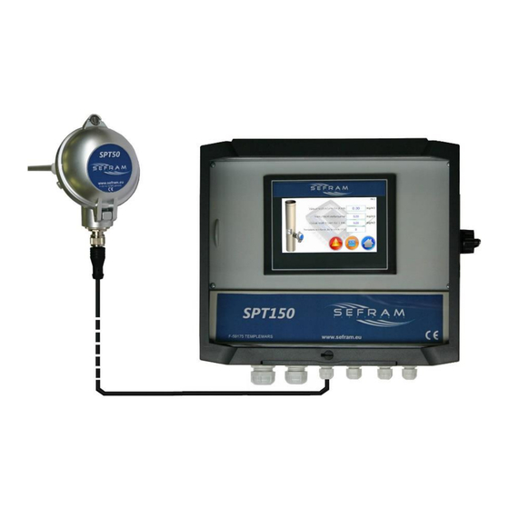
SOMMAIRE : DESCRIPTION : Page - DESCRIPTION The SPT150 is a dust emission controller based on the principle - CHARACTERISTICS of triboelectricity. It consists of two parts: - ASSEMBLY, DIMENSIONS AND a SPT50 sensor directly installed on the duct or conduit to be FIXING monitored. -
Page 3: Characteristics
DUST EMISSION CONTROLLER CARACTERISTIQUES : BASE : - Supply voltage (nominal voltage) : Two versions, the choice is made at ordering : AC Version : 100 to 240V 50/60Hz DC Version : 24VDC - Consumption (rated current) : AC Version : 60mA /240V - 120mA /100V DC Version : 300mA max - Protections : AC Version :... -
Page 4: Assembly, Dimensions And
DUST EMISSION CONTROLLER ASSEMBLY, DIMENSIONS AND FIXING: Sensor : The sensor is fixed directly to the duct to be monitored under the following conditions: - G1/2" thread - Placed in a straight section as shown in the diagram below, - On an earthed metal sheath, earth continuity must be ensured between the probe and the sheath section. Connect the probe to earth via the terminal on the body of the probe. - Page 5 DUST EMISSION CONTROLLER Cover locking screw Sensor head M20 gland Stainless steel locknut Cylindrical thread G1/2 Stainless steel link PTFE insulator 3 fixing screws of the rod ATEX version Technical manual FI 72.0577.0224E Page 5 / 27...
-
Page 6: Base
DUST EMISSION CONTROLLER Base : ISO20 : power supply ISO16b : relay outputs alert and alarm ISO12 : sensor connection ISO12 : 4-20mA output ISO12 : input Modbus customer communication ISO12 : output Modbus customer communication USB port Ethernet port (option) Fixings : (back view) Gland clamping capacity :... -
Page 7: Connections
DUST EMISSION CONTROLLER CONNECTIONS : Connections must be made with the power off. The connection terminals are accessible after removal of the connection cover (on the underside of the screen). The cable conductors must be flexible and have a cross-section of between 0.25 and 1.5 mm2. BASE : Please note: No sensor other than the SPT50 may be connected to the base, as this could damage the product. -
Page 8: Sensor
DUST EMISSION CONTROLLER Câbles : Préconisations Cable designation No. of conductors x cross-section mm² (minimum) Recommendations Power supply 3G1.5² - Recommended cable H07RN-F or equivalent complying with EN60227 or EN60245 - The EARTH conductor must be longer than the active conductors so that, in the event of a pull, the protective EARTH conductor is the last to be stressed. -
Page 9: 4-20Ma Output
Several SPT150s can be connected to the same Modbus network using an adjustable identifier. The SPT150 are then wired in series on the Modbus network. For wiring, the connection box has 2 glands (1 for the cable coming from the previous box and another for the cable going to the next box). -
Page 10: Setting / Calibration
DUST EMISSION CONTROLLER Bit11 : - reserved - Bit12 : Bit13 : Bit14 : Bit15 : Information on the unit used 0 : mg/m3 1 : g/m3 2 : µg/m3 3 : % Instantaneous rejection value Float type: 4 bytes (LOW part of the float) Float type: 4 bytes (HIGH part of the float) Average rejection value over X minutes Float type: 4 bytes (LOW part of the float) -
Page 11: User Interface
DUST EMISSION CONTROLLER USER INTERFACE: Start page : 1 : Company or manufacturer logo If the user does not take any action on the screen (press) for 5 seconds, the system automatically displays the main page on the screen. Main page : 1: Average value of dust emissions measured over X minutes. -
Page 12: Fault(S) In Progress Page
DUST EMISSION CONTROLLER fault(s) in progress page : 1: Time-stamped list of faults present. Indication of the number, time the fault occurred and designation. 2: reset the fault by pressing the icon 3: link to general menu General menu page : 1: link to main page 2: link to security page 3: link to HMI parameters page... -
Page 13: Graphics Page
DUST EMISSION CONTROLLER Graphics page : 1: Graph. The y-axis represents the value of the measurements (depending on the unit chosen; e.g. mg/m3). The x-axis represents time. 2: Validation / Devalidation display of the instantaneous rejection measurement curve. 3: Validation / Devalidation: display of the curve of rejection measurements averaged over 1 minute. 4: Validation / Devalidation display of the curve of rejection measurements averaged over X minutes. - Page 14 DUST EMISSION CONTROLLER Users are classified into 3 levels: level 0, level 1 and level 2. Levels 1 and 2 are password-protected. Access to certain functions or modification of certain parameters is possible depending on the protection level of the screen.
-
Page 15: Hmi Parameters Page
DUST EMISSION CONTROLLER HMI parameters page : 1: Screen brightness setting 2: Setting the calendar clock 3: Screen size calibration Necessary when the touch screen does not respond accurately 4 : USB key removal 5 : Link to main page 6 : link to general menu page Language page : 1 : English... -
Page 16: System Information Page
DUST EMISSION CONTROLLER System information page : 1: contact details of manufacturer, supplier 2: product name 3: box serial number 4: software version name, electronic board software no. / HMI software no. 5: link to main page 6: link to general menu page Technical manual FI 72.0577.0224E Page 16 / 27... -
Page 17: Fault History Page
DUST EMISSION CONTROLLER Fault history page : 1 : Fault history: Indication of the number, time of appearance and possible disappearance of the fault and designation. 2 : "USB recording" button (accessible in security level 1) The system enables the history of faults to be retrieved on a USB key. The system records the last 9999 faults. -
Page 18: Parameter Menu Page
DUST EMISSION CONTROLLER Parameter menu page : 1: Access to the measurement parameters page (unit, recording frequency, etc.) 2: Access to the relay output parameters page (choice of relay output information) 3 : Access the calibration page (product calibration) 4 : Access to the dedusting peak detection page 5: Access the thresholds page (alarm threshold settings) 6 : Access to customer com page (Modbus RS485 com settings) 7: Access to the 4-20mA analogue output page (4-20mA output settings) -
Page 19: Measurement Parameters Page
DUST EMISSION CONTROLLER Measurement parameters page : 1 : Choice of unit of measurement (accessible in safety level 2) : - mg/m , g/m , µg/m or % 2 : X: Current period over which the averaged value is calculated (accessible in security level 1) Adjustable from 1 to 30 minutes 3 : Measurement recording frequency. -
Page 20: Relay Output Parameters Page
DUST EMISSION CONTROLLER Relay output parameters page: Relay 1 settings 1: Information transmitted on relay output 1 (accessible in security level 1) Multiple choices possible 2: Link to parameters menu 3: Link to Relay 2 settings page Relay 2 settings 1: Information transmitted to relay output 2 (accessible in security level 1) Multiple choices possible 2: Link to Relay 1 settings page... -
Page 21: Calibration Page
It is essential to carry out this step simultaneously with the intervention of the approved centre in order to guarantee that the measurement conditions between those carried out by the SEFRAM product and those carried out by the centre are identical. -
Page 22: Dedusting Peak Detection Page
DUST EMISSION CONTROLLER Dedusting peak detection page : Detection of dedusting peaks involves looking at the instantaneous rejection value in relation to a defined threshold ("peak threshold"). 1: Validation of the dedusting peak function (accessible in level 2) 2: "Peak detected" threshold setting (accessible in level 2) If the instantaneous rejection value is above the set threshold, the system considers that the measured rejection peak is due to dedusting in progress. -
Page 23: Thresholds Page
DUST EMISSION CONTROLLER Thresholds page : 1 : "Dust emission alarm" setting threshold (accessible in level 1) 2 : Type of "Dust emission alarm" reset (accessible in level 1) 2 possible choices: automatic, i.e. as soon as the averaged value is below this threshold, the fault disappears manual cad the fault only disappears if the fault is manually reset and the averaged value is below the threshold 3 : "Dust emission alert"... -
Page 24: Customer Com Page
DUST EMISSION CONTROLLER Customer com page : Modbus RS485 communication 1 : Communication speed configuration (accessible in level 1) possible choices: 2400, 4800, 9600, 19200, 38400, 57600 and 115200 Bauds 2 : Configuration of the number of STOP bits: 1 or 2 (accessible in level 1) 3 : Parity: None, Even or Odd (accessible in level 1) 4 : Modbus identifier (setting from 1 to 241) (accessible in level 1) 5 : Link to parameters menu... -
Page 25: Faults
DUST EMISSION CONTROLLER FAULTS : Automatic Name Reasons Effects Actions to be taken reset ALARM: High internal Temperature measured inside the sensor - Risk of damage to the temperature > temperature alarm threshold sensor - check that the dust YES after Instantaneous measurement of dust collector handles are in tempo... -
Page 26: Precautions
FRANCE CONFORMITY: The SPT150 connection base complies with current European directives (EMC directives) to which it is subject. The SPT50 sensor complies with the current European directives (EMC directives) to which it is subject.However, a version conforming to the ATEX Directive is also available. -
Page 27: General Safety, Assembly
Before any intervention on the cabinet, the equipment must be In the event of a problem, please contact Sefram. de-energized by cutting off the power source upstream of it. V. MAINTENANCE II.
Need help?
Do you have a question about the SPT150 and is the answer not in the manual?
Questions and answers