
Related Manuals for HMS Intesis IN485UNI001I100


Summary of Contents for HMS Intesis IN485UNI001I100
- Page 1 Modbus RTU interface for infrared HVAC integration Compatible with IR-enabled AC units, from most brands USER MANUAL Issue date: 01/2024 v1.4 ENGLISH...
- Page 2 HMS Industrial Networks reserves the right to modify its products in line with its policy of continuous product development. The information in this document shall therefore not be construed as a commitment on the part of HMS Industrial Networks and is subject to change without notice. HMS Industrial Networks makes no commitment to update or keep current the information in this document.
-
Page 3: Table Of Contents
Intesis® MAPS Config Tool ......................14 6 Technical Specs ............................ 15 7 List of compatible AC indoor units......................16 © HMS Industrial Networks S.L.U. - All rights reserved https://www.intesis.com This information is subject to change without notice 3 / 16... -
Page 4: Presentation
The interface is USB-powered. If not connected to a computer for setting or testing routines from the Config Tool, the USB port should be feeding 5 Volts DC from the power adapter (included) © HMS Industrial Networks S.L.U. - All rights reserved https://www.intesis.com... -
Page 5: Device Installation
Different emplacements are Intesis IN485UNI001I100 acceptable, as shown in figures below. Figure 3.2 Wall mount. Figure 3.3 Wall / desktop mount. © HMS Industrial Networks S.L.U. - All rights reserved https://www.intesis.com This information is subject to change without notice 5 / 16... -
Page 6: Connection To Eia-485
Use the USB cable to connect the device to a computer running config software, for setting and testing purposes, or to the power adapter (included), for regular operation © HMS Industrial Networks S.L.U. - All rights reserved https://www.intesis.com This information is subject to change without notice... -
Page 7: Modbus Interface Specification
Magnitude for this register can be adjusted to Celsius x 1ºC, Celsius x 10ºC (default) or Fahrenheit. It is not possible turn to x10 the value shown in Fahrenheit. © HMS Industrial Networks S.L.U. - All rights reserved https://www.intesis.com This information is subject to change without notice... - Page 8 Lower limit for setpoint setting Parrot Mode ▪ 0: Not active ▪ 1: Active This value is stored in non-volatile memory © HMS Industrial Networks S.L.U. - All rights reserved https://www.intesis.com This information is subject to change without notice 8 / 16...
-
Page 9: Ac Startup Registers
Magnitude for this register can be adjusted to Celsius x 1ºC, Celsius x 10ºC (default) or Fahrenheit. It is not possible turn to x10 the value shown in Fahrenheit. © HMS Industrial Networks S.L.U. - All rights reserved https://www.intesis.com This information is subject to change without notice... -
Page 10: Device Registers
If the register is configured as “0:Non-blocked”, all commands received from Modbus will be sent to the AC system. If “1: Blocked”, commands from Modbus will only be sent to the AC system if they differ from the previous value. © HMS Industrial Networks S.L.U. - All rights reserved https://www.intesis.com... -
Page 11: Implemented Modbus Functions
DIP-switch block. Some Modbus RTU EIA-485 Master devices can provide also internal 120 Ω terminator resistor and/or fail-safe biasing. Check the technical documentation of the Master devices connected to the EIA-485 network in each case. © HMS Industrial Networks S.L.U. - All rights reserved https://www.intesis.com This information is subject to change without notice... -
Page 12: Configuration Settings
When Parrot mode is enabled, the device will simply emit every IR signal picked at by the receiver, acting as a repeater. Parrot mode is used for testing or troubleshooting to confirm the device location for AC control. © HMS Industrial Networks S.L.U. - All rights reserved https://www.intesis.com... -
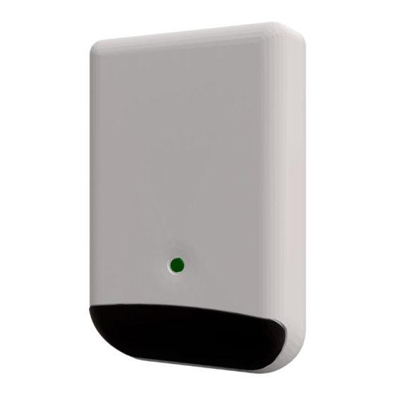
Page 13: Device Led Indicator
Device informs… Blinking RCF corruption (low intensity) Check Intesis Maps configuration manual to know how to overcome this error. © HMS Industrial Networks S.L.U. - All rights reserved https://www.intesis.com This information is subject to change without notice 13 / 16... -
Page 14: Intesis® Maps Config Tool
This interface in configured using Intesis Maps®. You can download this software for free in www.intesis.com. Please, review Intesis Maps IN485UNI001I100 user manual to learn how to configure the device using this software. © HMS Industrial Networks S.L.U. - All rights reserved https://www.intesis.com... -
Page 15: Technical Specs
1 x external LED – operational status Power consumption: max. 400mA @ 5 Vdc indicator Buttons 1 x Button © HMS Industrial Networks S.L.U. - All rights reserved https://www.intesis.com This information is subject to change without notice 15 / 16... -
Page 16: List Of Compatible Ac Indoor Units
If your AC unit or IR remote controller were not in the list, contact Intesis TS Team to confirm if the IR remote is already integrated or how to initiate the integration process. © HMS Industrial Networks S.L.U. - All rights reserved https://www.intesis.com...
Need help?
Do you have a question about the Intesis IN485UNI001I100 and is the answer not in the manual?
Questions and answers