Table of Contents
Advertisement
Quick Links
INSTRUCTION MANUAL
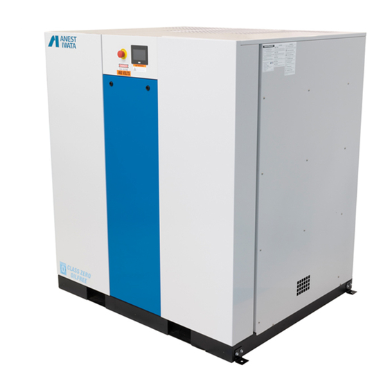
OIL-FREE SCROLL COMPRESSOR
SLE-50
SLE-60
Thank you for purchasing our oil-free scroll air compressor.
●Before operation, be sure to read this instruction manual thoroughly for safe
and efficient use for a long operating lifetime.
●After reading it, store in a convenient place for immediate and future
reading.
Before use, be sure to fill in the blank spaces below for future repair and after service.
MODEL
SERIAL No.
Purchased from
Date of purchase
Date of use
Advertisement
Table of Contents

Related Manuals for Anest Iwata SLE-50


Summary of Contents for Anest Iwata SLE-50
- Page 1 INSTRUCTION MANUAL OIL-FREE SCROLL COMPRESSOR SLE-50 SLE-60 Thank you for purchasing our oil-free scroll air compressor. ●Before operation, be sure to read this instruction manual thoroughly for safe and efficient use for a long operating lifetime. ●After reading it, store in a convenient place for immediate and future reading.
-
Page 2: Important Information And Safety Precautions
Important information and Safety precautions ▪ Important information Read all important information and safety precautions before use. The operator shall be fully knowledgeable of the requirements stated within this instruction manual, including important warnings, cautions and operation. Read manual before performing any maintenance. Keep this booklet in an appropriate place for immediate reference. -
Page 3: Safety Precautions
Important information and Safety precautions ▪ Safety precautions WARNING Install in a safe area. To prevent a fire or explosion, install in an area free of flammable gases or organic solvents. Never install outdoors. To prevent fire or electric shock, never install outdoors. Turn off the main electric source. - Page 4 Important information and Safety precautions WARNING Not for use as life support. Serious bodily injury and/or death may occur. Unit must only be used to compress air. Do not touch. Keep hands and fingers away from fans, pulleys and belts while the power is on. Serious injury, including entanglement of fingers or hands can occur.
- Page 5 Important information and Safety precautions CAUTION Use at ambient temperatures of 36°F to 104°F. Drain will freeze at less than 36°F and will cause unit failure. Using over 104°F will cause a shorter lifespan or unit damage. Use in an area free of dirt and dust. Failure to do so may result in equipment failure.
-
Page 6: Table Of Contents
Contents ■Software version ----------------------------------------------- Important information and Safety precautions ■Unit ID ------------------------------------------------------------- 38 ■Important information -------------------------------- ■Data log and Recipe ------------------------------------------- ■Safety precautions ------------------------------------- ■Alarm log --------------------------------------------------------- Problems and remedies ■Contents -------------------------------------------------- ■Caution displays ----------------------------------------------- ■Compressor -------------------------------------------------- Before use ■Inspect the product ------------------------------------ Maintenance and inspection ■Transportation ------------------------------------------ ■Compressor maintenance standards --------------------- 43... -
Page 7: Before Use
Before use ▪ Inspect the product • Inspect the product to be sure you have the model you ordered. Scroll 50HP 208; 208V 60HP 230; 230V Enclosure 460; 460V Three phase N/A; 115psi (Maximum pressure) 145psi (Maximum pressure) • Check that there is no deformity or damage which occurred during transportation. Any shipping damage must be immediately filed with the freight carrier. -
Page 8: Transportation
Before use ▪ Transportation • Transportation by forklift Use holes for forklift on both sides of compressor. Do not puncture panel with tips of forklift. • Transportation by crane Use holes for forklift as illustrated and lift up by wire. Be sure to use pads in order to protect panels. -
Page 9: Installation
Installation ▪ Precautions about installation あ Do not install Do not use in an area which is exposed to rain, steam or high humidity. High humidity can cause electric shock or fire. Do not install in an area with corrosive gas (ammonia, acid, ozone gas and sulfur dioxide) to prevent a shorter lifespan. -
Page 10: Installation Space
The following ventilation volume is necessary in order to keep temperature increase inside room to 9°F above room temperature. When the static pressure is zero, select the actual figure larger than the figures in the chart below. SLE-50 SLE-60 Model... - Page 11 When installing the exhaust duct, take precautions to minimize pressure loss of duct, and attach the ventilation fan at the exhaust section. Keep distance between the duct inlet and exhaust of the compressor to 8 - 12 inches for easy maintenance. SLE-50 SLE-60 Model...
-
Page 12: Piping
(4) Installing an air receiver is optional. When purchasing an air receiver, select a receiver larger than the following capacity. SLE-50, SLE-50H; 300 Gallon SLE-60, SLE-60H; 400 Gallon ❖ In case the differential is changed to 15 psi, the volume of the air receiver must be 1.5 times larger than the recommendation at 22 psi. -
Page 13: Electrical Wiring
Installation ▪ Electrical wiring ❖ Precautions about wiring た Turn off main electric source before inspecting or wiring. Deviation from this instruction can cause electric shock or serious bodily injury. い Only a qualified electrician should perform repairs to prevent electric shock or fire. い... - Page 14 Unit load Non-time Time delay circuit each total delay fuse fuse breaker (FLA) (FLA) SLE-50 30.8 – 28 166 - 151 450 - 400 300 - 300 450 - 400 SLE-50H SLE-60 30.8 – 28 197 - 179 500 - 450...
-
Page 15: Test Operation
Test operation ▪ Operation ❖ Preparation (1) Check to be sure the air receiver piping has been firmly connected. (2) Open the ball valve of the compressor air outlet. (3) Turn on the main electric source and be sure the display section of the operating panel lights up. - Page 16 Operate the unit while the ball valve of the air receiver is closed. Be sure the compressor stops at the pressure shown below. Model Max. pressure (psi) SLE-50, SLE-60 SLE-50H, SLE-60H ❖ Check minimum control pressure When maximum pressure is reached and compressor stops, open outlet valve and gradually reduce pressure.
-
Page 17: Check Control
Multi-stage control ❖ This figure is an example of the operation of SLE-40 and SLE-40H. SLE-50 and SLE-50H operate 5 air ends and SLE-60 and SLE-60H operate 6 air ends. (2) Prevention of long-term operation When the operating time of the an air end exceeds the set time, it changes operation from that air end to the one which has stopped, preventing long-term operation of one air end. - Page 18 Operating panel ▪ Changing the HMI Internal Clock The HMI system clock is set to default by the manufacturer. During an alarm event the alarm log screen displays occurrence time and date as well as alarm message. The occurrence time and date correspond to the HMI system time and date, therefore it is recommended to change the HMI system clock to correspond to the local time zone.
- Page 19 Operating panel 4. Go to Clock Setting 5. Set date and time to correspond to the local time zone...
- Page 20 Operating panel ▪ Main Screen Current pressure at the outlet of the compressor Run Mode selection buttons Alarm light Compressor status indicator E-Stop light and reset button ▪ Operation and stop ❖ Operation Press the ON switch so the compressor operating lamp lights up and compressor immediately starts. ❖...
- Page 21 Operating panel ▪ Status Screen Pump Details buttons Run status indicator lamps Lead pump display Sensor Reset button View next status screen Total unit runtime ▪ Run status indicator lamps ❖ RUN Lamp is green when pump is running and gray when pump or compressor is off. ❖...
- Page 22 Operating panel ▪ Ambient Temperature PLC Error Code Ambient Temp in ° F PLC Error Reset The compressor is equipped with an ambient temperature sensor located on the back of the unit, For efficiency and durability, the ambient temperatures of the compressor must fall between 36°F & 104° F. Operating in less than 36°F will cause unit failure or freezing, while operating in over 104°F will cause a shorter lifespan or unit damage.
- Page 23 Operating panel ▪ Pump Details Screen Current temperature reading of the pump. Below are the warning and Motor overload status lamp and shutdown thresholds. reset button Run time of the pump Next and Back buttons to cycle through all pumps Temperature warning/shutdown reset button ▪...
- Page 24 Operating panel ▪ Sensor Resets Screen Temp sensor status lamps and reset buttons Pressure sensor status lamp and reset button Next button to cycle through all sensors ▪ Reset buttons ❖ Temp Sensors Lamp is green when status is ok, red when the sensor has failed, and gray when the compressor is off. If red, check wiring or replace the sensor then press this reset button.
- Page 25 Operating panel ▪ Alarm Screen Alarm identification messages Time and date of the alarm occurrence Main Button will return you to the Main screen These buttons control the cursor in the Alarm screen ▪ Alarm Screen control buttons ❖ SELECT This button makes the cursor appear and disappear.
- Page 26 Operating panel ▪ Settings 1 Screen Numerical inputs for the differential parameters Numerical inputs for the high pressure parameters Calculated values of the low pressure parameters Next button to reach the second setting screen Buttons to switch between P1 and P2 settings Note: •...
- Page 27 Operating panel ▪ Settings 2 screen Auto Restart toggle buttons Switch Lock toggle buttons Remote Start toggle buttons Button to reach the Units screen Back button to reach the previous setting screen Button to reach the Clock screen ▪ Settings Screen toggle buttons ❖...
- Page 28 Operating panel ▪ Units screen Buttons to choose units of pressure. Back button to reach the previous screen Note: • The compressor must be turned off before converting units of pressure.
- Page 29 Operating panel ▪ Clock screen Buttons to choose format of date display Button to set the values from inputs to the clock Back button to reach the previous screen Numerical inputs for Month, Day, Year, Hour, Minute, and Second Note: •...
- Page 30 Operating panel ▪ Maintenance Note screens. Note explaining maintenance schedule Next and Back buttons to cycle between the Note Screens and the Maintenance screens Note explaining the maintenance time counters...
- Page 31 Operating panel ▪ Maintenance screen Maintenance warning/shutdown time counters and reset buttons for each pump Next button to cycle between Maintenance screens Button to reach the Maintenance Log Numerical input for changing maintenance time Note: • Pump reset buttons and maintenance time input are locked by a password...
- Page 32 Operating panel ▪ Maintenance Log screen Time, Date, Pump #, Pump runtime, total compressor time Next and Back buttons to cycle through all pages The current Maintenance Log page number Note: • The previous 12 pump reset occurrences are kept in the Maintenance Log. After that, older entries are deleted.
- Page 33 Operating panel ▪ Password screen Numerical input to enter the password Lock symbol disappears with correct password Back button to reach the previous screen Numerical input to set a new password Note: • The default password is: 45011 • To bring up the change password field, enter: 45211...
- Page 34 ➢ Introduction BACnet/IP Communication is available through ethernet port # 1, Customers can connect their BACnet system to our compressor using Ethernet cable. Note: • A convenient front panel ethernet plug is optional (contact ANEST IWATA AIR ENGINEERING for more info)
- Page 35 Communication ➢ Object List Our Compressor can deliver a various Status and Alarm to BACnet/IP network, the object lists are divided into two main sections Analog Input Objects and Binary Input Objects. Note: • All objects are read only, and no data can be written to the PLC The Analog Input Objects are the analog values collected from the compressor and sent to the network with values and Units: ✓...
- Page 36 Communication To change the BACnet setting: 1- Press SET and a BACnet setting Screen will Popup 2- First disable BACnet 3- Change Device ID and Port number 4- Enable BACnet Note: • BACnet setting cannot be modified without disabling the Communication...
- Page 37 Communication The BACnet status section demonstrate the system health, the table below summarize all possible status values: Status Description 0 : BACnet Prohibited BACnet Communication Status 1 : BACnet Permitted 0 : Stopped 1 : Ready BACnet Operation Status 2 : Operating 3 : Stopped by Error 0 : No Error 1 : Invalid device ID...
- Page 38 Default IP Address: 192.168.1.5 Default Subnet Mask: 255.255.255.0 Default gateway: N/A Note: • To change the PLC IP Address please follow the steps above (BACnet section) • To view all Modbus addresses, please contact ANEST IWATA AIR ENGINEERING for the Modbus addressing table...
-
Page 39: Software Version
Communication ▪ Software version This section shows the electrical drawing version along with the software versions of the HMI and PLC programs ▪ Unit ID Operator can assign a unit identification to each unit. Unit ID consist of four characters including letters, numbers, and special characters. -
Page 40: Data Log And Recipe
PLC. • Please keep SD memory card and USB attached unless advised by ANEST IWATA Air Engineering. • If the SD memory card is missing an alarm will be triggered indicating the SD memory card is missing from the PLC. -
Page 41: Alarm Log
Data log and alarm log will assist in troubleshooting and determining the state and history of the compressor as well as updating PLC/HMI software. • Please keep SD memory card and USB attached unless advised by ANEST IWATA Air Engineering. -
Page 42: Problems And Remedies
Problems and remedies ▪ Alarm displays (1) When the alarm flashes on the display screen, the compressor may stop. The display will keep flashing until the alarm is reset. (2) Check the Alarm Screen. (3) When an alarm appears, cut off the main breaker, solve the issue, and turn on the electric source. Reset the alarm. (4) Refer to the chart below: •... - Page 43 Problems and remedies If you have any problems, please refer to the chart below. If the (*) marked items are difficult for you to fix, please contact the shop you purchased it from. ▪ Compressor Problems Causes Remedies • • Electric source is not turned on.
-
Page 44: Compressor Maintenance Standards
Maintenance and inspection Carry out the following maintenance and inspection items according to the schedule below. This interval is based on conditions where ambient temperature is at around 86°F. If your location is warmer or running condition is severe, maintain at a shorter period. 30% from our recommendation at every 9 degree F. The maintenance time differs from guarantee period. -
Page 45: Daily
Maintenance and inspection To keep your compressor in good condition for a long time, you must conduct proper inspection and maintenance. Consider periodic inspection as a minimum standard, shortening the time if necessary. ▪ Daily • Drain the condensate from the air receiver. Activate the drain valve of air receiver before releasing compressed air in air receiver, and Drain condensate from air receiver. - Page 46 Maintenance and inspection • Safety valve Lift the stem of the safety valve at about maximum pressure and blow it off. Then push the stem down. • Check ventilation fan Check the ventilation fan to see if it rotates correctly and exhausts air during compressor operation.
- Page 47 Maintenance and inspection ▪ Every 2,000 hours or yearly • Replace the intake filter. フィルタ Filter • Check the belt tension. See if the V belt makes a slipping sound at the startup, due to decrease of the V belt tension. If so, readjust the belt tension or replace it.
-
Page 48: Every 2000 Hours Or Yearly
Maintenance and inspection • Check leakage Close the stop valve at the air receiver outlet and push the operating switch of the compressor to operate. When all compressors stop operation at maximum pressure, push the stop switch and check the air pressure of the operating panel. - Page 49 Specifications ▪ Compressor specifications ▪ 50 HP Model SLE-50 SLE-50H Item Pump model SL-210 x 5 SL-2101 x 5 Control system Multi-stage (Pressure start-stop detected by sensor) Discharge pressure (psi) 94 to 116 123 to 145 Air delivery (cfm) 143.7...
- Page 50 Specifications • 60 HP Model SLE-60 SLE-60H Item Pump model SL-210 x 6 SL-2101 x 6 Control system Multi-stage (Pressure start-stop detected by sensor) Discharge pressure (psi) 94 to 116 123 to 145 Air delivery (cfm) 172.5 Driving system V-belt Discharge air temperature Intake temperature (degree F)
- Page 51 Appendix ▪ Outer dimensions • SLE-50/50H and SLE-60/60H...
- Page 52 Please refer to the attached circuit diagram. ▪ HMI setting Item Minimum Factory setting Maximum Upper Pressure (psi) (SLE-50 / SLE-60) Differential (psi) (SLE-50 / SLE-60) Lower Pressure (psi) (SLE-50 / SLE-60) Upper Pressure (psi) (SLE-50H / SLE-60H) Differential (psi)
- Page 53 Appendix ▪ Menu flow chart...
- Page 54 SHALL ANEST IWATA AIR ENGINEERING BE LIABLE FOR ANY INCIDENTAL, CONSEQUENTAL, PUNITIVE, SPECULATIVE OR INDIRECT LOSSES OR DAMAGES WHAT SO EVER ARISING OUT OF OR IN ANY WAY RELATED TO ANY OF THE PRODUCTS OR GOODS SOLD OR AGREED TO BE SOLD BY ANEST IWATA AIR ENGINEERING TO BUYER. TO THE EXTENT ALLOWABLE UNDER APPLICABLE LAW, ANEST IWATA AIR ENGINEERING’S LIABLITY IN ALL EVENTS IS LIMITED TO AND SHALL NOT EXCEED THE PURCHASE PRICE...
- Page 55 ANEST IWATA AIR ENGINEERING, Inc. www.anestiwata.com inquiry@anestiwata.com Toll Free (800)440-0282 No. SLE60-99 rev2.3...
Need help?
Do you have a question about the SLE-50 and is the answer not in the manual?
Questions and answers