Table of Contents
Advertisement
Quick Links
Monoblock DC Inverter Series
User Manual
Air source swimming
pool heat pump
Heating+Cooling
Attention
Thank you for choosing our product, we shall be more than glad to service you. For you to better operate this
product and to prevent accidents due to misoperation, please read carefully this user manual before carrying
out any installation or operation, also please pay special attention to the warning, prohibition and attention
instructions. We are continuously supplementing and upgrading this user manual to better service for you!
Advertisement
Table of Contents

Related Manuals for SPRSUN CGY015V3


Summary of Contents for SPRSUN CGY015V3
- Page 1 Monoblock DC Inverter Series User Manual Air source swimming pool heat pump Heating+Cooling Attention Thank you for choosing our product, we shall be more than glad to service you. For you to better operate this product and to prevent accidents due to misoperation, please read carefully this user manual before carrying out any installation or operation, also please pay special attention to the warning, prohibition and attention instructions.
-
Page 2: Table Of Contents
Contents User Manual Part 1. Before use..................2 1. Attentions..................2 2. Internal structure of unit............4 3. wiring diagram................7 4. Primary circulation system ............9 Part 2.Use....................14 1. Buttons function...............14 2. Key operation instructions............15 Part 3.WIFI module networking manual..........19 1. APP download and install............19 2. -
Page 3: Part 1. Before Use
Part 1. Before Use 1. Attentions This appliance is not intended for use by persons, including Be sure to read this manual before use. children, with reduced physical, sensory or mental capabilities, or lack of experience and knowledge, unless they have been given supervision or instruction concerning use of the appliance by a person responsible for their safety. - Page 4 Use a dedicated socket for this unit, otherwise malfunction may Do not touch the air outlet grill when fan motor is running. occur. When running the unit, never cover clothes, plastic cloth or any Water or any kind of liquid is strictly forbidden to be poured into other material that block ventilation on the product which will the product, or may case creepage or breakdown of the product.
-
Page 5: Internal Structure Of Unit
2. Internal structure of unit Component Component Chassis Fan support Titanium tube heat exchanger Finned evaporator DC compressor Electrical box Middle diaphragm Frequency converter Rear service panel Evaporator cover plate Power inlet hole Cover Pressure gauge Cover plate of electrical box Air outlet network front panel Air outlet frame... - Page 6 Step 1: first rem ove the 1-2-3 screw s Step 2: push back the 4 top cover, and then the fixing the top cover, w ater outlet plate top cover w ill com e out. W e can see the inside and rear screen plate of the m achine and the refrigerant filling port 17 18 19 20...
- Page 7 Detail I Step 8: remove the screws 25-26-27-28-29-30 at the Step 7: remove the 23-24 screws at position shown in the figure, and then remove the the position shown in the figure to rear air outlet net take out the control panel 31 32 33 34 35 Step 10: remove the screws 36-37-38-39-40-41-42 at the Step 9: remove the screws...
-
Page 8: Wiring Diagram
Ambient Air temperature After throttle temp Inlet gas Air HE coil Low pressure switch Water inlet temp Water flow switch Outlet gas High pressure switch B A GND 12V B A GND 12V 1、 FOR CGY010V3/CGY015V3/CGY020V3/CGY025V3/CGY030V3/CGY035V3/CGY040V3 Voltage: 220V~240V/50Hz or 60 Hz/1Ph. - Page 9 2、 FOR CGY050V3/CGY060V3 , Voltage: 220V~240V/50Hz or 60 Hz/1Ph...
- Page 10 3、FOR CGY-050V3/CGY-060V3 , Voltage: 380V~420V/50Hz or 60 Hz/3Ph...
- Page 11 Input Power supply Power supply L1 L2 L3 380V~ 220V~ Output Output Max. Max. Line(mm ) Line(mm ) Model Model Current(A) Current(A) CGY-050V3 CGY015V3 11.48 CGY-060V3 CGY020V3 13.2 CGY-080V3 CGY025V3 17.1 CGY030V3 13.1 CGY035V3 16.2 CGY040V3 21.8 CGY050V3 CGY060V3 29.9...
-
Page 12: Primary Circulation System
5、Primary circulation system Swimming pool Swimming heat pump Ball valve PUMP Hair collector Sand filter cylinder Potion Air source swimming pool heat pump For all Model... - Page 13 • The heat pump must be installed in open space. Normally is installedon the roof of house. • The unit should be placed in dry and well-ventilated environment. If the environment is humid, electronic components may get corroded orshort circuit. •...
- Page 14 there are plenty of water flow down too. • Heat pump should far away from kitchen exhaust, because thefinned tube is not easy to clean if there is oil on it.
- Page 15 ≥ 500 ≥ 500 Ground Back ≥ 500 ≥ 500 Right side Left side Front For all Model...
- Page 16 • Heat pump must be installed on flat concrete blocks or a raisedconcrete platform, or steel bracket. Between heat pump and basic or bracket, at leas • 4pcs anti-shockpads should be placed Steel bracket Concrete basic Anti-shock pad Expansion bolt •...
-
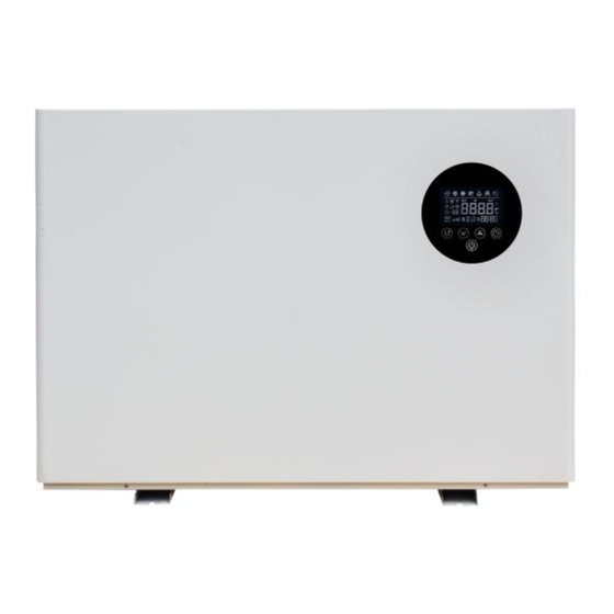
Page 17: Part 2.Use
Part 2. Use LED color screen line controller: Icon introduction : Heating mode“ ” Cooling mode“ ” Silent mode : “ ”; Smart mode : “ ”; Strong mode : “ ”。 When defrosting , “ ”... -
Page 18: Key Operation Instructions
operation . When Wi-Fi connection is successful “ ”light stays on, flashing when not connected or connected. Screen is locked “ ”. When a fault is reported “ ”Flashing . Key operation instructions : 1、“ ”power button : Short press“... - Page 19 Query Representative meaning Display range code Inlet water temperature -30~99℃ Outlet temperature -30~99℃ Ambient temperature -30~99℃ Exhaust gas 0~125℃ temperature Return air temperature -30~99℃ Outer coil temperature -30~99℃ Inner coil temperature -30~99℃ Main expansion valve opening Enthalpy expansion valve opening Compressor current Heat sink temperature DC bus voltage value...
- Page 20 “ ”the hour decreases by one. If you hold down the“ ”or“ ” key for a long time, the hour will automatically increase or decrease. After setting the hour digit value, press the“ ”button again; at this time, the minute digit flashes, indicating that the minute value of the current time can be adjusted by the“...
-
Page 21: Part 3.Wifi Module Networking Manual
When entering the defrost, the flashing display “ ”。 7、Frequency mode switching: In the boot interface, press “ ”to switch the frequency mode: silent, smart, and strong mode. 8、Celsius/Fahrenheit switch: In the shutdown state, long press“ ”and“ ” for 3 seconds in the main interface to switch between Celsius/Fahrenheit. - Page 22 Android System IOS System...
-
Page 23: Start The App
2. Start the APP After the installation, click the “ ” icon on the desktop to start the software. Smart Life... -
Page 24: Register And Login
3. Register and Login 3.1 Register Users without account can apply by clicking the "Register"function on the login page: Register Agree the privacy policy Enter the mobile number Get the veri fication code Enter the verification code Set the password Complete, as shown in the following figure: ... - Page 25 3.2 Login You can login directly if you have the account , the sequence as follows:...
- Page 26 If you forget the passport ,you can choose the authentication number to login. Choose “aut hentication number logon enter phone no get the authentication number. As follow: After creating a family or login, enter the interface of App Intelligent Life.
-
Page 27: Wifi Module Networking
4. WIFI module networking Step 1 The heat pump manually enters the smart distribution grid mode: within 10S after power-on, press and hold the “switch”,“ ”,“timing” three buttons 5S at the same time to enter the smart distribution grid mode, the “WIFI” icon flashes, phone can start distribution grid. - Page 28 Step 3 “Add Device” interface, confirm that the line controller has selected the smart distri bution mode. After the “WIFI” icon is flashing, click “Confirm indicator is flashing”; Enter the WIFI connection interface, enter the WIFI password that the mobile phone has connected (must be consistent with the WIFI connected to the mobile phone and the WIFI must be 2.4G WIFI), click OK to enter the device connection status directly.
- Page 29 erface of the device.
-
Page 30: App Operation Instructions
5. APP Operation Instructions... - Page 31 Modify the device name Click “Device Details” in the following order and click “Device Name” to rename the device name. Device sharing Share the bound devices, and the sharers operate in the following order. After the sharing is successful, the list increases to show the shared person.
- Page 32 Enter the shared account and click “Finish”. The sharing success list shows the newly added account.
- Page 33 The interface of the shared person as below, showing the shared deviced is received, then chick to enter can ooperate the control device. Mode setting Click “ ” mode switch on the main interface of the device operation, and the mode selection interface will pop up as shown below.
- Page 34 Timer setting Click “ ” on the main interface of the device operation, and enter the timing setting interface. As shown in the figure below, click Add Timing.
- Page 35 Enter the timing settings, sliding up and down hours/minutes can set the timing time, and set the repetition week and turn/turn, according to the upper right corner can be saved, as shown in the following order;...
- Page 36 Remove device Remote control removal When the device has been added,if you need to remove the device, long press " " plus plus " " 5S, the device is removed and re-entered into the smart distribution network mode.The“WIFI” icon flashes within 3 min to re-configured the network.
- Page 37 “WIFI” icon flashes within 3 min to re-configured the network. If it exceeds 3 min, the network will be quit. Remove APP Click on the top right corner of the device operation main interface“ ”Enter the device details interface. Click “Remove Device” on the device details interface to enter the smart distribution network mode.The “WIFI”...
-
Page 38: Other Problem And Repairig
6. Other problem and repairig Error Possible reason Method 1. Power supply cable is 1. Cut off the power Heat pump loose supply to check and doesn’t run 2. The fuse of power repair. supply is fused. 2. Change the fuse. 1. - Page 39 1. Expansion valve 1. Change expansion damaged lead to liquid valve Compressor entering compressor 2. Change compressor noise is 2. The internal parts of 3. Compensate oil for loud compressor damaged compressor 3. Compressor lack of oil 1. Fan blade fixing screw is 1.
- Page 40 Warranty card Product model: Bar code: Buyer Address Invoice Date Repair Repair record Repairer date...
-
Page 41: Warranty
Items of warranty: 1. Warranty terms: ; Within warranty, any problem because of quality, please contact us for support. 2. When repair needed, please show the warranty card and invoice of order or other proof. 3. We don’t afford the problem that is caused by re-fitment or adding other function by user. - Page 43 NO.11801011 CERTIFICATE Product Model: Bar code:...
Need help?
Do you have a question about the CGY015V3 and is the answer not in the manual?
Questions and answers