
Related Manuals for SPRSUN CGK/C-9


Summary of Contents for SPRSUN CGK/C-9
- Page 1 CGK/C-9 220V/50Hz/1ph (Product No: A11244) Installation manual Air source heat pump (heating + hot water) PCB No: CG248027 Operating panel No: CG248028...
-
Page 2: Safety Precaution
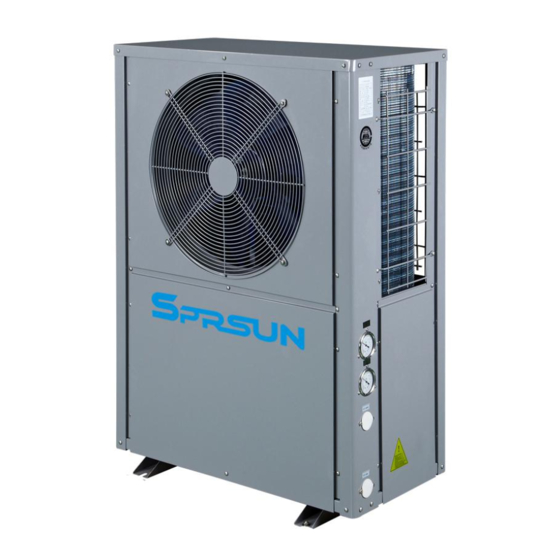
Safety precaution To avoid electrical shock, make sure to disconnect power supply 1minute or more before operating the electrical part. Even after 1minute, always measure the voltage at the terminals of main circuit capacitors or electrical parts and, before touching, make sure that those voltages are lower than the safety voltage. - Page 3 To know the product from exterior Air inlet Air outlet High pressure gauge Low pressure gauge Water outlet Water inlet Electric box plate Cable holes...
- Page 4 Important parts in heat pump...
- Page 5 Important parts in heat pump Code Name Remarks Ambient temp sensor Connect to port CN11 on PCB Outlet gas temp sensor Connect to port CN12 on PCB Inlet gas temp sensor Connect to port CN8 on PCB Air heat exchanger coil temp Connect to port CN9 on PCB sensor Outlet water temp sensor...
- Page 6 Heat pump size Back view Right view Front view Left view...
-
Page 7: Installation Diagram
Installation diagram Room thermostat Special valve for floor heating loop AC water Water separator Hot water tank water outlet tank NRV3 Water collector Connect to Connect to city water city water NRV1 NRV2 Floor heating Heat pump... -
Page 8: Introduction Of The System
Introduction of the system 1. Hot water tank temp sensor (T1) The sensor should be put in the sensor tube which is installed in hot water tank. 2. Floor heating water temp sensor (T2) 2.1 Floor heating temp sensor has been installed on the inlet water pipe inside heat pump before leave factory. - Page 9 Introduction of the system 5. Three way valve (3WV): 5.1 Three way valve is controlled by heat pump controller. 5.2 When room linkage switch is connected: hot water is priority, means if both hot water side and floor heating side need be heated, the three way valve will change to hot water side, until hot water tank reach preset temp, then the valve will change to floor heating side.
- Page 10 Introduction of the system 8. About hot water tank 8.1 Because the three way valve, a coil heat exchanger must be installed in hot water tank. Otherwise, the sanitary hot water will be mixed with floor heating water. 8.2 The coil heat exchanger capacity should be about 18KW. And the inner diameter of coil should be ≥DN25.
- Page 11 Heat pump installation notes The heat pump must be installed in open space. Normally is installed on the roof of house. The unit should be placed in dry and well-ventilated environment. If the environment is humid, electronic components may get corroded or short circuit. Heat pump mustn’t be installed in the environment where corrosive, volatile, or flammable liquid or gas exists.
-
Page 12: Installation
2. Installation 2.4 Distances to barrier and ground Top side Front Back side side ≥2m ≥0.5m Ground Top side Front Back side side ≥0.5m ≥1m Ground... - Page 13 Other notes of installation Heat pump must be installed on flat concrete blocks or a raised concrete platform, or steel bracket. Between heat pump and basic or bracket, at leas 4pcs anti-shock pads should be placed Anti-shock pad Steel bracket Concrete basic Expansion bolt 3) Before make basic or bracket, please check heat pump dimension...
-
Page 14: Wiring Diagram
Wiring diagram motor Transformer room linkage 4-way valve Primary Linkage OUT1 OUT2 OUT3 OUT4 OUT5 OUT6 OUT7 OUT8 Water pressure switch Water flow switch AC-N High pressure switch Fan motor high pressure switch Electric expansion valve capacitance Low pressure switch low pressure switch Instant + cycle 1 phase... - Page 15 Terminal details of wiring F a c t o r y s i d e I n s t a l l e r s i d e 1. Floor heating valve: When floor heating side work, 3-way valve coil get electricity. The terminal supply 220V/1ph voltage.
-
Page 16: Water Flow Switch
5. Floor heating electric heater: Max carrying current is 6A. 220V/50Hz/1ph. (This terminal is optional, it can be chassis electric heater of heat pump too. When place your order from factory, If select there is chassis electric heater, then floor heating electric heater will not be included, but will change to chassis electric heater) 6. -
Page 17: Analog Signal Input
Analog signal input CN2 CN3 CN6 CN8 CN9 CN11 CN12 CN13 CN14 Communication: connect operating panel Tank: Hot water tank temp sensor (installer should install the probe in tank) Outlet water: Outlet water temp sensor (has been installed in heat pump) Air HE coil: Source side (air) heat exchanger coil temp sensor (has been installed in heat pump) Outlet gas: outlet gas temp sensor of compressor (has been installed in heat pump) -
Page 18: Power Supply
Power supply terminal block Output Power Supply Input Voltage: 220V~240V/50Hz/1Ph Size of power supply line: Max working current: 17A L line: 1.5mm Circuit breaker: 32A N line: 1.5mm... -
Page 19: Room Thermostat
Wiring diagram of all room thermostat control water pump (P2) For floor heating system, if want P2 (heating system water pump) stops when all floor heating loops needn’t work, can connect all the room thermostat to P2h, the wiring diagram as below. Water separator Floor heating water separator... - Page 20 Wiring diagram of all room thermostat connect to room linkage terminal If want heat pump only performs at hot water side when floor heating side no need, can connect all room thermostats to “Room linkage” terminal. Water separator Floor heating water separator Room 20C°...
Need help?
Do you have a question about the CGK/C-9 and is the answer not in the manual?
Questions and answers