Advertisement
Table of Contents
- 1 Table of Contents
- 2 Part 1 before Use
- 3 Attentions
- 4 Installation
- 5 Heat Pump Installation Location and Attentions
- 6 Installation Diagram and Tips
- 7 Pre-Stat up
- 8 Part 2. Use
- 9 Operation and Display
- 10 Data Query and Setting
- 11 Error Code
- 12 Working Modes
- 13 Electrical Component Controlling
- 14 Part 3.Maintenance and Reparing
- 15 Warranty Card
- Download this manual
Heat Pump User Manual
Comprehensive version
(EVI heat pump and High temp. heat pump)
Version: CG2017111601
This manual is suitable for below heat pumps:
No
Abbreviations
1
EVI-HW
2
EVI-HH
3
EVI-HC
4
HT
Note: Abbreviations name will be used in the below content, pls check the
related content for your heat pump referring to the form above.
Details
EVI air source heat pump hot
water series
EVI air source heat pump
heating + hot water series
EVI air source heat pump
heating and cooling series
Air source high temperature
heat pump
Model
CGK/C-XX(L),
CGK/D-XX(L)
CGK/C-XX(L),
CGK/D-XX(L)
CGK/C-XX(LHC),
CGK/D-XX(LHC)
CGK/C-XX(H),
CGK/D-XX(H)
Advertisement
Table of Contents

Related Manuals for SPRSUN CGK/C-XX(L) Series


Summary of Contents for SPRSUN CGK/C-XX(L) Series
- Page 1 Heat Pump User Manual Comprehensive version (EVI heat pump and High temp. heat pump) Version: CG2017111601 This manual is suitable for below heat pumps: Abbreviations Details Model EVI-HW EVI air source heat pump hot CGK/C-XX(L), water series CGK/D-XX(L) EVI-HH EVI air source heat pump CGK/C-XX(L), heating + hot water series CGK/D-XX(L)
-
Page 2: Table Of Contents
Contents Part 1. Before use …….…………………………………………………2-6 A. Attentions ....................2 B. Installation ....................4-6 Heat pump installation location and attentions……………………………….….4 Installation diagram and tips…………………………...………………………...5 Pre-stat up………………………………………………………………………..6 Part 2. Use …………………………………………….….……………….7-21 Operation and display…………………………………………………..…….9-12 Data query and setting……………………………………………………...…..13 Error code………………………………………………………………………14 Working modes…………………………………………………………………19 Electrical component controlling……………………………………….………21 Part 3.Maintenance and Reparing ………………………………...23-26 Warranty card………………………………………………………………...26... -
Page 3: Part 1 Before Use
Part 1 Before Use Attentions... -
Page 5: Installation
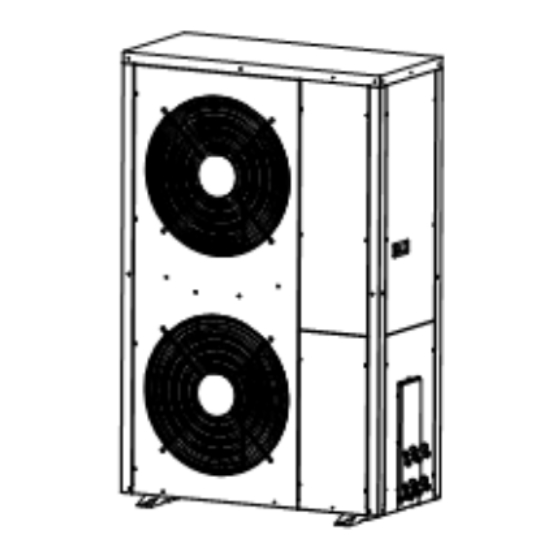
2.Installation A. Heat pump installation location and attentions *. Heat pump is not allowed to be installed in the place where combustible gas may leaks. *. Heat pump is not allowed to be installed in the place where there is oil or corrosion gas released. -
Page 6: Installation Diagram And Tips
* for hot water and floor heating *for heating/cooling... -
Page 7: Pre-Stat Up
Tips for installation related to the water pipe part: *Install a valve at the highest point of each water circulations for releasing air from water system. * A Y filter is very important in front of circulating water pump of heat pump. * If more heat pumps installed in one water pipe system, the connection of these heat pumps can’t be in series, only can be in parallel or independent. -
Page 8: Part 2. Use
Part 2. Use Operating panel display EVI-HC A. Heating mode B. Cooling mode... - Page 9 EVI-HH A. Only hot water mode B. Heating + hot water mode...
-
Page 10: Operation And Display
EVI-HW HT series... - Page 11 Buttons function ↓ ↓ ↓ ↓ ↓ Clock power “Power” button 2.1.1 Under unlock state, press this button for 1second, can turn on and turn off heat pump. 2.1.2 Under other state, press this button, can return main interface. 2.1.3 Under locking state, press this button for 5 seconds, can unlock buttons. “M”...
- Page 12 (if there is not operating on buttons for 60sec, buttons will be locked automatically, and displays lock symbol) Turn on/off heat pump. Press “power” button, if operating panel shows off state, will turn on heat pump. If operating panel shows on state, will turn off heat pump. Water tank temperature setting (L3 or L4) Except EVI-HH and HH series, other series have two way to set water tank temperature:...
- Page 13 Table 1: heat pump working status parameters query Code Meaning Note Water tank temperature Outlet water temperature Air heat exchanger 1 lowest Same meaning for all series tube temp Inlet gas temperature of Same meaning for all series compressor 1 Outlet gas temperature of Same meaning for all series compressor 1...
-
Page 14: Data Query And Setting
tube temp Outlet gas temperature of Same meaning for all series compressor 2 Inlet gas temperature of Same meaning for all series compressor 2 After throttling 2 temperatures Inlet economic unit 2 Outlet economic unit 2 Compressor 2 current Same meaning for all series Primary electronic expansion For HW and HH and SP-H series, valve opening degree 2... -
Page 15: Error Code
Table 2: Error code Code Meaning Method Er 01 Wrong phase error Exchange phase sequence Er 02 Lack phase error Check the power supply Check the hot water side of the water flow is sufficient or the water flow Er 03 Water flow switch error switch wiring, such as damage please replace Check the hot water side of the water... - Page 16 too high System (2) Outlet gas Er 13 pressure of compressor 2 is too high Check the sensor contact is good; Er 14 Throttling temperature 1 replace the temp sensor Er 15 Throttling temperature 2 Air heat exchanger 1 coil Er 16 as above temp sensor...
- Page 17 high protection Check the wiring contact is good; replace Er 31 Water level switch error the pressure switch Ambient temp too low Beyond the normal operating temperature Er 32 protection range of the heat pump Outlet water temp too high Check the sensor contact is good;...
- Page 18 Setting Code Meaning Factory setting range Compressor restart temperature 3℃ 2℃─18℃ of hot water drop 1. HT series: 75℃ Preset water tank temperature of 2. EVI-HC series: 45℃ 20℃─58℃ heating mode 3. Other series: 55℃ Compressor restart temperature 5℃ 2℃─18℃ cooling drop Preset water tank temperature of 12℃...
- Page 19 ① Clock setting A. At main interface, press “clock” button for 5 seconds, enter clock setting interface B. At clock interface, press “clock” button, then “hour” flash, press “+”or “-”button, can set hour. C. After finish setting hour, press “clock” button, then “minute” flash, now press “+”or“-”button,can set minute.
-
Page 20: Working Modes
group 3 and 4 only valid for EVI-HW, HT series. I. How to cancel timer? At timer interface, press “clock” button for 5seconds, when the ON and OFF signal disappear, then press “power” button to confirm, can cancel current group ON/OFF timer. -
Page 21: Electrical Component Controlling
2.2.2 Heating mode The unit start and stop based on the heating return temp. and the setting temp. 2.2.3 Hot water + floor heating controlling logic ◆ Hot water is priority, before hot water reach preset temp, 3-way valve doesn’t have electricity ◆... - Page 22 2. Four - way valve (installed inside heat pump) 2.1 At heating or hot water mode, 4-way valve lose electricity. 2.2 When cooling or defrosting, four-way valve get electricity. 2.3 Four way valve delay 2min change direction after compressor stop when change working mode.
- Page 23 5.4 Except there is water level error, hot water tank temp sensor error, when there is other temp error, high and low pressure error protection, electric heater will start. Remarks: EVI-HH series, only hot water side has electric heater function, heating side doesn’t have.
-
Page 24: Part 3.Maintenance And Reparing
Part 3. Maintenance and repairing A. Daily maintenance Heat pump is high automatic equipment, if can check and maintain periodically, the stability and lifetime of heat pump will increase greatly. 1. When using and maintain the heat pump, please note: all security device have been set before leave factory, please don’t adjust anymore. - Page 25 remove barrier close air inlet or outlet. 1. Lack of refrigerant 1. Repair leakage and refill 2. Water pump is too refrigerant Outlet gas temp small 2. Change a bigger water pump too high error 3. Water pipe is too small 3.
- Page 26 supply is fused. 2. Change the fuse. 1. Refrigerant is not 1. Check leakage and enough repair and refill gas 2. Water system insulating 2. Improve the Heating capacity is not good insulation is too small 3. Air heat exchanger is 3.
-
Page 27: Warranty Card
Warranty card Product model: Bar code: Buyer Address Invoice No. Date Repair date Repair record Repairer Items of warranty: 1. Warranty term: ; Within warranty, any problem because of quality, we repair for free. 2. When need repair, please show the warranty card and invoice of order or other proof. - Page 28 3. We don’t afford the problem that is caused by re-fitment or adding other function by user. 4. Warranty card and invoice or other purchasing proof will be invalid if alerted. 5. Please keep the warranty card and invoice or other purchasing proofs good, we will not supply service if these documents are lost.
Need help?
Do you have a question about the CGK/C-XX(L) Series and is the answer not in the manual?
Questions and answers
wat is de werking ( temp afh weerstand , thermokoppel, halfgeleider) vd tempvoelers en hoe kan ik de kabels verlengen , Ik hoor graag van u