Advertisement
Quick Links
IM No CEX8TF004EN-A
ORIGINAL INSTRUCTIONS
Instruction Manual
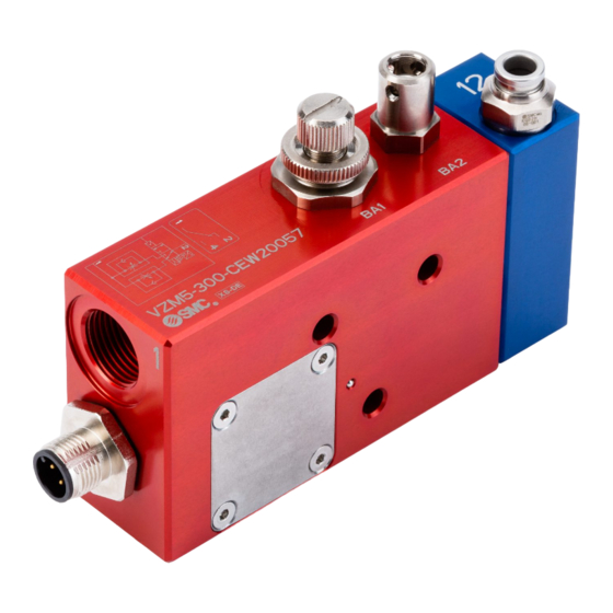
Two speed valve with spool position switch
VZM5-300-CEW20057 with 1 inlet port
VZM5-310-CEW20057 with 2 inlet ports
Safety component as defined by the Machinery Directive 2006/42/EC
article 2c/ The Supply of Machinery (safety) Regulations 2008 part
2.4(2)(c)
The intended use of this product is to control the speed of an actuator by
switching between the operating speed (BA1) and the safely limited speed
(BA2).
Reasonably foreseeable misuse
Mixing up the throttle and incorrect setting of the two throttles.
Refer to the drawings for additional information.
1 Safety Instructions
These safety instructions are intended to prevent hazardous situations and/or
equipment damage. These instructions indicate the level of potential hazard
with the labels of "Caution," "Warning" or "Danger."
They are all important notes for safety and must be followed in addition to
International Standards (ISO/IEC)
*1)
, and other safety regulations.
*1)
ISO 4414: Pneumatic fluid power - - General rules relating to systems.
ISO 4413: Hydraulic fluid power - - General rules relating to systems.
IEC 60204-1: Safety of machinery - -Electrical equipment of machines.
(Part 1: General requirements)
ISO 10218-1: Manipulating industrial robots -Safety.etc.
• Refer to product catalogue, Operation Manual and Handling Precautions
for SMC Products for additional information.
• Read this manual before using the product, to ensure correct handling, and
read the manuals of related apparatus before use.
• Keep this manual in a safe place for future reference.
• To ensure safety of personnel and equipment the safety instructions in this
manual must be observed, along with other relevant safety practices.
Caution indicates a hazard with a low level of risk
Caution
which, if not avoided, could result in minor or
moderate injury.
Warning indicates a hazard with a medium level
Warning
of risk which, if not avoided, could result in death
or serious injury.
Danger indicates a hazard with a high level of risk
Danger
which, if not avoided, will result in death or
serious injury.
1 Safety Instructions - continued
Warning
• The compatibility of the product is the responsibility of the person
who designs the equipment or decides its specifications.
Since the product specified here is used under various operating
conditions, its compatibility with specific equipment must be decided by the
person who designs the equipment or decides its specifications based on
necessary analysis and test results. The expected performance and safety
assurance of the equipment will be the responsibility of the person who has
determined its compatibility with the product. This person should also
continuously review all specifications of the product referring to its latest
catalogue information, with a view to giving due consideration to any
possibility of equipment failure when configuring the equipment.
• Only personnel with appropriate training should operate machinery
and equipment.
The product specified here may become unsafe if handled incorrectly.
The assembly, operation and maintenance of machines or equipment
including our products must be performed by an operator who is
appropriately trained and experienced.
• Do not service or attempt to remove product and machinery/
equipment until safety is confirmed.
1) The inspection and maintenance of machinery/equipment should only
be performed after measures to prevent falling or runaway of the driven
objects have been confirmed.
2) When the product is to be removed, confirm the safety measures as
mentioned above are implemented and the power from any appropriate
source is cut, and read and understand the specific product precautions of
all relevant products carefully.
3) Before machinery/equipment is restarted, take measures to prevent
unexpected operation and malfunction.
• Do not use this product outside of the specifications.
• Contact SMC beforehand and take special consideration of safety
measures if the product is to be used in any of the following
conditions.
1) Conditions and environments outside of the given specifications or use
outdoors or in a place exposed to direct sunlight.
2) Installation on equipment in conjunction with atomic energy, railways,
air navigation, space, shipping, vehicles, military, medical treatment,
combustions and recreation, or equipment in contact with food or
beverages, emergency stop circuits, clutch and brake circuits in press
applications, safety equipment or other applications unsuitable for the
specification described in this document.
3) An application which could have negative effects on people, property or
animals requiring special safety analysis outside the scope of EN ISO
13849 described in this document.
4) Use in an interlock circuit, which requires the provision of double
interlock for possible failure by using a mechanical protective function, and
periodical checks to confirm proper operation.
• Always ensure compliance with relevant safety laws and standards.
• All electrical work must be carried out in a safe manner by a qualified
person in compliance with applicable national regulations.
Caution
• The product is provided for use in manufacturing industries.
This product must not be used in residential areas.
The product herein described is basically provided for peaceful use in
manufacturing industries.
If considering using the product in other industries, consult SMC
beforehand and exchange specifications or a contract if necessary.
If anything is unclear, contact your nearest sales branch.
Warning
Always ensure compliance with relevant safety laws and standards.
All work must be carried out in a safe manner by a qualified person in
compliance with applicable national regulations.
2 Specifications
Warning
Special specification products "-X###" and "-##" might have specifications
different from those shown in this Instruction Manual.
Refer to individual drawings for special specifications.
2 Specifications - continued
VZM5-300-CEW20057
Modell
VZM5-310-CEW20057
G3/8
Port size
Fluid
compressed air
Operating pressure range
0.1 to 0.7 MPa
Proof pressure
1.05 MPa
0.15 – 0.7 MPa
Pilot pressure range
5 μm or less
Air quality required
Min. operating frequency
1 cycle/30days
Max. operating frequency
30 cycles/min.
Ambient and fluid temperature
-5 to +60°C (no freezing)
Note 1)
Impact resistance
1000 m/s² at 11 ms duration
Vibration resistance
Note 2)
50 m/s
2
(0.35 mm)
Sonic conductance (C)
1.1 dm³/(s.bar)
Rated voltage
Note 3)
24 V DC +/- 10%
Rated current (non-inductive
0.5 A (fuse 2AgG)
Note 4)
load)
IP rating
IP67
B10
9.4 million cycles
D
Table 1
Note 1) Two axes (horizontal and vertical) and two directions were tested and no
malfunction of the valve occurred (pulse shape: sin shape, axial direction and
rectangular to the product, 3 times for each condition (pilot port not pressurised)
Note 2) Two axes (horizontal and vertical) and two directions were tested and no
malfunction occurred in a sweep cycle test between 10 to 150 Hz at vibration sweep
0.35mm (pilot port not pressurised). Impact and vibration test perfomed before lifetest
with new product.
Note 3) The derate factor of 2.5 has already been used for the rated voltage.
Note 4) The system designer should derate the rated current according to safety
requirements.
Note 5) The B
figure is estimated from SMC life tests under SMC test conditions.
10D
2.1 Schematic diagram (M12) - IP-Rating Electrical limit switch (IP67)
Electrical symbol
Connector
Safety switch
Pin no.
Wire color
1
BN (brown)
4
BK (black)
2
WH (white)
3
not connected
Table 2
The switch is connecting pin 1 and 2 in the safe state.
2.2 Safe and unsafe state
The de-energized air operated pilot valve (safe state) enables the air flow for
the safely limited speed of the actuator and the switch is connecting pin 1 and
2. The energized air operated pilot valve (unsafe state) enables the air flow
for the operating speed of the actuator and the switch is connecting pin 1 and
4. The switch is activated by positive mechanical action from "safe state" to
"unsafe state".
The valve spool is spring/air returned. A malfunction of the valve spool non-
returning into the safe state will be detected by the PLC according to the
signal of the switch.
2.3 Pneumatic symbols
2 Specifications - continued
2.4 Declaration of Conformity - CE
Note 5)
2.5 Declaration of Conformity – UK CA
Page 1 of 1
Advertisement

Subscribe to Our Youtube Channel
Related Manuals for SMC Networks VZM5-300-CEW20057


Summary of Contents for SMC Networks VZM5-300-CEW20057
- Page 1 Proof pressure 1.05 MPa VZM5-300-CEW20057 with 1 inlet port determined its compatibility with the product. This person should also continuously review all specifications of the product referring to its latest 0.15 –...
- Page 2 Thread Model No. or steam are present. G 3/8 with 1 inlet port VZM5-300-CEW20057 • Do not use in an explosive atmosphere. G 3/8 with 2 inlet ports VZM5-310-CEW20057 • Do not expose to direct sunlight. Use a suitable protective cover.
Need help?
Do you have a question about the VZM5-300-CEW20057 and is the answer not in the manual?
Questions and answers