Table of Contents

Related Manuals for Dormakaba ALVARADO Argus V60

Summary of Contents for Dormakaba ALVARADO Argus V60
- Page 1 Compact Optical Turnstile Argus V60 Installation Instructions Alvarado dormakaba Group 12660 Colony Street, Chino, CA 91710 Phone: +1 (909) 591-8431 Fax: +1 (909) 628-1403 support@alvaradomfg.com www.alvaradomfg.com PUD4736R1-0...
-
Page 2: Table Of Contents
Argus V60 Installation Instructions Contents Information about this document ........................3 Content and purpose ..........................3 Target group ............................. 3 Other applicable documents ........................3 Orientation in the document ........................4 Abbreviations ............................4 Change log ............................... 5 Symbols used ............................6 1.7.1 Danger categories ........................ -
Page 3: Information About This Document
1 Information about this document Content and purpose This manual describes the sensor barrier Argus V60 from dormakaba. This manual is part of the operating instructions according to the Machinery Directive 2006/42/EC. This manual must be carefully read and understood before starting any work. Complying with all safety instructions and action steps provided in this manual is the basic prerequisite for safe working. -
Page 4: Orientation In The Document
Control board (Elektronische Türsteuerung or electronic door control, io = input/output) LVX2CAN-K3 Processing board Escape route solution SafeRoute Escape route solution from dormakaba DCW bus Bus system (Dorma Connect and Work): For networking SafeRoute components SLI (Basic) SafeRoute License card (license level) -
Page 5: Change Log
Argus V60 Installation Instructions Companies/organizations CENELEC European Committee for Electrotechnical Standardization Canadian Securities Administrators organization for safety and performance standards as well as certification Fachverband Türautomation (Association for Door Automation) International Electrotechnical Commission International Classification for Standards International Standardization Organization Underwriters Laboratories (North American safety standards) Verband der Elektrotechnik (Association for Electrical, Electronic &... -
Page 6: Symbols Used
Argus V60 Installation Instructions Symbols used 1.7.1 Danger categories DANGER Describes an imminent danger resulting in serious injury or death. WARNING Describes a potentially dangerous situation that may result in serious injury or death. CAUTION Describes a potentially dangerous situation that may result in minor injury. NOTICE Describes a potentially damaging situation in which the product or something in its vicinity may be damaged or that could result in malfunction. -
Page 7: Symbols (Unit)
Argus V60 Installation Instructions 1.7.3 Symbols (unit) The symbols shown can be found on the unit. The electrical voltage symbol is located on or next to components that can carry mains voltage. The symbol Main protective conductor connection is located next to components that are a main protective conductor connection. -
Page 8: Security
Risk of injury due to insufficient personnel qualification Insufficiently qualified personnel are not able to assess the risks associated with handling the unit and may expose themselves and others to the danger of severe injury, including death. If unqualified personnel work on the unit or are located in the danger area of the unit, there are dangers that may cause severe injuries and significant property damages. • Arrange for all work described in this manual to be carried out by dormakaba personnel or companies appointed by dormakaba. • K eep insufficiently qualified personnel away from the danger areas. • If anything is unclear, contact dormakaba. Due to their qualifications, the personnel know the necessary personal protective equipment and wear it without being asked when carrying out the activities. -
Page 9: Product Description
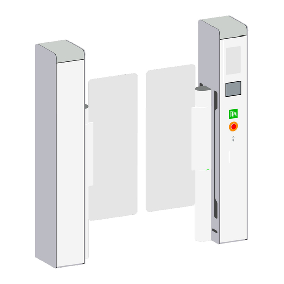
Argus V60 Installation Instructions 3 Product description Overall view 3.1.1 Argus V60 Moving barrier Status light (optional) RA10-M05 drive and locking device Sensor window Chasing light (optional) Cover, front Card reader (optional) Cover, side Document reader (optional) Cover SafeRoute (optional) Page 9 support@alvaradomfg.com +1 (909) 591-8431... -
Page 10: Identification Label
Argus V60 Installation Instructions Identification label The manufacturer dormakaba’s identification plate has the following standardized structure. The basis for the labelling is the Machinery Directive with its national implementations as well as the Construction Products Regulation. The stickers attached to the unit and the individual components must not be removed or damaged. Manufacturer's address in full Area for conformity and certification marks; see Symbols (identification plate) [... -
Page 11: Environmental Conditions
Temperature range: +41 to +104°F [+5°C to +40°C] NOTICE Impairment of unit functions under extreme conditions Extreme conditions include high humidity, aggressive air (e.g. salty), extreme temperatures and dirt. • A technical clarification must be implemented with dormakaba before order placement Technical specifications 3.4.1 Argus V60 Power supply... -
Page 12: Delivery And Transport
By default, deliveries are delivered individually packaged on a pallet. Other solutions are also possible depending on the project and customer requirements. These customer requirements must be agreed when ordering with the dormakaba contact. Inspection on delivery The scope of delivery is documented in one or more enclosed packing lists. The composition of the parts depends on the order. -
Page 13: Mounting
Risk of injury due to insufficient personnel qualification Insufficiently qualified personnel are not able to assess the risks associated with handling the unit, and may expose themselves and others to the danger of severe injury, including death. If unqualified personnel work on the unit, or are located in the danger area of the unit, there are dangers that may cause severe injuries and significant property damages. • Works detailed in this instruction manual may only be carried out by personnel employed by dormakaba or trained according to their specifications. • C heck Personnel qualification [ 2.1]! • K eep insufficiently qualified personnel away from the danger areas. -
Page 14: Requirements For The Floor
Argus V60 Installation Instructions 5.2.2 Requirements for the floor WARNING Risk of fire caused by technical errors Technical errors within the unit could lead to a fire that could spread to the surrounding area. • The unit must be placed on a flame-retardant floor. 5.2.2.1 Check floor properties Do not lay any heating coils or supply cables in the area of fixing holes. Flooring properties (example) Finished floor level Floor covering Moisture barrier Floor screed Footfall sound insulation C oncrete floor S ub floor level CAUTION Danger of injury and possible material damage The unit will not be stable or functional if it is installed on a floor that cannot support dowels. Further Danger zones may arise and the unit may be damaged. -
Page 15: Tools And Auxiliary Materials
Argus V60 Installation Instructions 5.2.3 Tools and auxiliary materials Parameterization requires Pavis3 in the latest version and with a valid license. Standard tools • Percussion drill • Masonry drill set • Spirit level • Folding rule 2 m • Screwdriver set Clamping tool (on •... -
Page 16: Preparatory Work
Argus V60 Installation Instructions Preparatory work 5.3.1 Lay conduits The cables and conduits must be positioned and laid according to the site plan before the foundation is poured. Designation Line type Function On-site cables (blue area) Mains connection Equipotential bonding Cables inside the unit (green area) NOTE These cables are laid together in an empty M40 conduit. - Page 17 Argus V60 Installation Instructions Notes about cabling • The cables are laid in conduits. This makes it easier to carry out future changes/expansions. • Only use cables with approval for the respective substrate/wall. • Observe national requirements. • U se flexible lines. •...
-
Page 18: Dismantle Covers
Argus V60 Installation Instructions 5.3.2 Dismantle covers Remove the two lower screws from the front cover of the side element. Attach a glass suction cup to the front cover of the side element. Slide the cover up. If there is a card reader, document reader, status light or SafeRoute, disconnect the connected cables. Tip the cover out. -
Page 19: Align Unit
Argus V60 Installation Instructions 5.3.3 Align unit Units must be aligned if a deviation has been detected in the chapter Check floor evenness [ 5.2.2.2]. Use the supplied underlay plates to align the unit if the ground is uneven. 5.3.3.1 Align single unit For the alignment of a single unit, a 3 m long aiming stake, a spirit level and a yardstick are required. M ark the mounting points on the floor. -
Page 20: Mount The Unit On The Floor
Argus V60 Installation Instructions Mount the unit on the floor During mounting, make sure that the installed sensors’ receivers and transmitters are in the correct position in relation to each other and that persons can be detected correctly. The unit can be mounted according to one of the following installation variants. •... -
Page 21: Affix The Unit To The Finished Floor
Argus V60 Installation Instructions 5.4.2 Affix the unit to the finished floor C lean the finished floor. Apply a 1/16" [2 mm] thick layer of adhesive (item. no. 191 111 69) to the adhesive plate. Under the adhesive plate there are spacers (3) with a height of 1/16" [2 mm], which ensure an adhesive gap of 1/16"... -
Page 22: Mount Components
Argus V60 Installation Instructions Mount components 5.5.1 Mount moving barrier Align the RA10 tooth clutch Place the zero point (1) and 0° axis mark (2) on top of each other. The zero point of the rotary encoder and the mechanical zero point are located on one axis. -
Page 23: Mounting The Covers
Argus V60 Installation Instructions 5.5.2 Mounting the covers If there is a card reader, document reader, status light or SafeRoute, connect the cables. Insert the post cover diagonally from below into the base frame and tilt the hook inside into the eyelet of the upper cover. Attach the two lower screws of the post cover. -
Page 24: Disposal
Risk of injury due to insufficient personnel qualification Insufficiently qualified personnel are not able to assess the risks associated with handling the unit, and may expose themselves and others to the danger of severe injury, including death. If unqualified personnel work on the unit, or are located in the danger area of the unit, there are dangers that may cause severe injuries and significant property damages. • Works detailed in this instruction manual may only be carried out by personnel employed by dormakaba or trained according to their specifications. • C heck Personnel qualification [ 2.1]! • K eep insufficiently qualified personnel away from the danger areas. -
Page 25: Disposal Of Old Units
Argus V60 Installation Instructions Disposal of old units Disassembly of the unit may only be carried out by suitably qualified personnel. dormakaba Deutschland GmbH units are fully recyclable. The regional and country-specific disposal regulations apply. • Separate all materials by type according to the following criteria: – Steel – Stainless steel – Aluminium – Glass – Electrical and electronic components All parts must be disposed of by certified waste removal companies. -
Page 26: Index Of Keywords
Argus V60 Installation Instructions Index of keywords Other Applicable Documents ..........3 Abbreviations ..............4 Align Units Align Single Unit ............19 Personnel Qualification ...........8 Align Multiple Or Special Units ........19 Assembly Requirements For Mounting ........13 Qualification ..............8 Auxiliary Materials ............15 Personnel ..............8 Conduits ...............16 Security ................8 Storage .................12 Symbols ................6... - Page 27 Argus V60 Installation Instructions Notes Page 27 support@alvaradomfg.com +1 (909) 591-8431 www.alvaradomfg.com PUD4736R1-0...
- Page 28 12660 Colony Street, Chino, CA 91710 Telephone: (909) 591-8431 Fax: (909) 628-1403 support@alvaradomfg.com www.alvaradomfg.com 2023 Alvarado dormakaba Group This work may not be reproduced, published or redistributed, in whole or in part, without the express prior written permission of Alvarado. PUD4736R1-0...
Need help?
Do you have a question about the ALVARADO Argus V60 and is the answer not in the manual?
Questions and answers