Sign In
Upload
Download
Table of Contents
Contents
Add to my manuals
Delete from my manuals
Share
URL of this page:
HTML Link:
Bookmark this page
Add
Manual will be automatically added to "My Manuals"
Print this page
×
Bookmark added
×
Added to my manuals
Manuals
Brands
GMI Manuals
Relays
D5039SD
Instruction manual
GMI D5039SD Instruction Manual
Intrinsically safe isolators and safety relays
Hide thumbs
1
Table Of Contents
2
3
4
5
6
7
8
9
10
11
12
13
14
15
16
17
18
19
20
page
of
20
Go
/
20
Contents
Table of Contents
Bookmarks
Table of Contents
Table of Contents
Mechanical Features
Mounting and Removing Modules from DIN-Rail
Power Bus Connector
Mounting Modules on Power Bus Connector
Ordering Information
Removing and Mounting Main Case Top Cover
Transparent Cover
Terminal Blocks Connection Data
Installation and Removing Modules from Termination Board
Mounting Termination Board
Mounting and Removing Termination Board Onto DIN-Rail
Termination Boards Characteristic
Approvals and Certifications
Storage
Disposal
Maintenance and Repair
Installation of Electronic Equipments in Cabinet
Heat Dissipation in Cabinets
Calculation of Radiant Surfaces in Closed Cabinets
Placement of Isolators in Cabinet
Advertisement
Quick Links
Download this manual
D5000 - D5200 Series
INSTRUCTION MANUAL
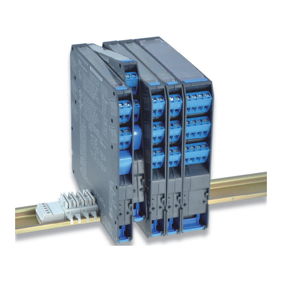
D5000 - D5200 SERIES
DIN-RAIL, POWER BUS,
TERMINATION BOARD MOUNTING
INTRINSICALLY SAFE ISOLATORS
SAFETY RELAYS
AND
D5000 - D5200 Series - Intrinsically Safe Isolators and Safety Relays
ISM0121-3
Table of
Contents
Previous
Page
Next
Page
1
2
3
4
5
Advertisement
Table of Contents
Need help?
Do you have a question about the D5039SD and is the answer not in the manual?
Ask a question
Questions and answers
Related Manuals for GMI D5039SD
Relays GMI D5000 Series Safety Instructions
Intrinsically safe isolators and relays, power supplies (80 pages)
Computer Hardware GMI D5200 Series Instruction Manual
Din-rail, power bus, termination board mounting (20 pages)
Relays GMI D5000 Series Instruction Manual
Din-rail, power bu ail, power bus, termination board mounting intrinsically safe ically safe isolators and safety relays (20 pages)
Repeater GMI D5037S Instruction & Safety Manual
Sil 2 switch/proximity detector repeater transistor out, din-rail and termination board (11 pages)
Media Converter GMI D6072S Instruction Manual
Sil 2 multifunction temperature converter. din-rail and termination board (10 pages)
Repeater GMI D5038S Series Instruction Manual
(8 pages)
Repeater GMI D5093S Instruction Manual
Sil 3 loop powered 24 to 220 vac/vdc switch repeater transistor out, din-rail and termination board (8 pages)
Repeater GMI D5093S-TB Instruction & Safety Manual
Sil3 24/220vdc/vac transistor-out detector (7 pages)
Power Supply GMI D5015SS Instruction Manual
Sil 2 repeater power supply hart, din-rail and termination board (6 pages)
Control Unit GMI D5096S-100 Instruction Manual
5 a sil 3/sil 2 sc3 relay module for ne or f&g/nd load, with diagnostic & universal fault mirroring din-rail and termination board (5 pages)
Relays GMI D5094S-104 Instruction Manual
Sil3 relay low-volt module for 5 a ne/nd loads din-rail and termination board (5 pages)
Relays GMI D5095S-105 Instruction Manual
Sil3 relay low-volt module for 5 a ne/nd loads din-rail and termination board (5 pages)
Relays GMI D5096S Instruction Manual
5 a sil 3 no contact relay output module for ne or f&g/nd load, with open/short circuit diagnostic din-rail and termination board (5 pages)
Relays GMI D5097S Instruction Manual
5 a sil 3 nc contact relay output module for ne or f&g/nd load, with open/short circuit diagnostic din-rail and termination board (5 pages)
Relays GMI D5295S Instruction Manual
5 a sil 3 nc contact relay output module for ne or f&g/nd load, with full diagnostic and modbus, din-rail, power bus and termination board (8 pages)
Relays GMI D5095S Instruction Manual
5 a sil 3 nc contact relay output module for ne or f&g/nd load, din-rail and termination board (5 pages)
This manual is also suitable for:
D5200 series
D5000 series
D5011s
D6072s
D5093s
D5038dd
...
Show all
D5093s-tb
D5037s
D5020s
D5015ss
D5096s-100
Table of Contents
Print
Rename the bookmark
Delete bookmark?
Delete from my manuals?
Login
Sign In
OR
Sign in with Facebook
Sign in with Google
Upload manual
Upload from disk
Upload from URL


Need help?
Do you have a question about the D5039SD and is the answer not in the manual?
Questions and answers