Table of Contents
Advertisement
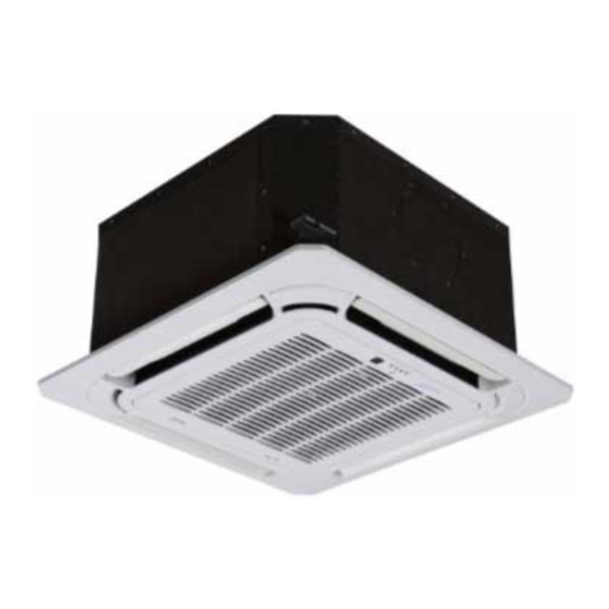
45MBCAQ
Split-Type Four-Way Cassette Indoor Unit Ductless System
Sizes 9K, 12K, 18K, 24K, 36K, 48K
NOTE: Read the entire instruction manual before starting the
installation.
TABLE OF CONTENTS
SAFETY CONSIDERATIONS . . . . . . . . . . . . . . . . . . . . . . . . . . . . . 1
ACCESSORIES . . . . . . . . . . . . . . . . . . . . . . . . . . . . . . . . . . . . . . . . . 7
Model Numbers . . . . . . . . . . . . . . . . . . . . . . . . . . . . . . . . . . . . . . . . . 7
DIMENSIONS . . . . . . . . . . . . . . . . . . . . . . . . . . . . . . . . . . . . . . . . . . 8
CLEARANCE . . . . . . . . . . . . . . . . . . . . . . . . . . . . . . . . . . . . . . . . . 10
PRODUCT INSTALLATION . . . . . . . . . . . . . . . . . . . . . . . . . . . . . 11
ELECTRICAL DATA . . . . . . . . . . . . . . . . . . . . . . . . . . . . . . . . . . . 16
CONNECTION DIAGRAMS . . . . . . . . . . . . . . . . . . . . . . . . . . . . . 16
DRAINPIPE INSTALLATION. . . . . . . . . . . . . . . . . . . . . . . . . . . . 17
REFRIGERANT PIPING CONNECTION . . . . . . . . . . . . . . . . . . . 18
WIRING PRECAUTIONS . . . . . . . . . . . . . . . . . . . . . . . . . . . . . . . 22
INDOOR UNIT WIRING . . . . . . . . . . . . . . . . . . . . . . . . . . . . . . . . 22
PANEL INSTALLATION. . . . . . . . . . . . . . . . . . . . . . . . . . . . . . . . 23
TEST RUN. . . . . . . . . . . . . . . . . . . . . . . . . . . . . . . . . . . . . . . . . . . . 25
PACKING AND UNPACKING THE UNIT . . . . . . . . . . . . . . . . . 25
TROUBLESHOOTING . . . . . . . . . . . . . . . . . . . . . . . . . . . . . . . . . . 26
DUCTLESS START-UP CHECKLIST - Single Zone . . . . . . . . . . 28
Installation Instructions
Specifications subject to change without notice.
SAFETY CONSIDERATIONS
Installing, starting up, and servicing air-conditioning equipment can
be hazardous due to system pressures, electrical components, and
equipment location (roofs, elevated structures, etc.).
Only trained, qualified installers and service mechanics should install,
start-up, and service this equipment.
Untrained personnel can perform basic maintenance functions such as
coil cleaning. All other operations should be performed by trained
service personnel.
When working on the equipment, observe precautions in the literature
and on tags, stickers, and labels attached to the equipment.
Follow all safety codes. Wear safety glasses and work gloves. Keep a
quenching cloth and fire extinguisher nearby when brazing. Use care
in handling, rigging, and setting bulky equipment.
Read these instructions thoroughly and follow all warnings or
cautions included in literature and attached to the unit. Consult local
building codes and National Electrical Code (NEC) for special
requirements. Recognize safety information.
This is the safety-alert symbol
When you see this symbol on the unit and in instructions or manuals,
be alert to the potential for personal injury. Understand these signal
words: DANGER, WARNING, and CAUTION. These words are
used with the safety-alert symbol.
DANGER identifies the most serious hazards which will result in
severe personal injury or death.
WARNING signifies hazards which could result in personal injury or
death.
CAUTION is used to identify unsafe practices which may result in
minor personal injury or product and property damage.
NOTE is used to highlight suggestions which will result in enhanced
installation, reliability, or operation.
.
Advertisement
Table of Contents

Related Manuals for Carrier 45MBCAQ


Summary of Contents for Carrier 45MBCAQ
-
Page 1: Table Of Contents
45MBCAQ Split-Type Four-Way Cassette Indoor Unit Ductless System Sizes 9K, 12K, 18K, 24K, 36K, 48K Installation Instructions SAFETY CONSIDERATIONS Installing, starting up, and servicing air-conditioning equipment can be hazardous due to system pressures, electrical components, and equipment location (roofs, elevated structures, etc.). - Page 2 45MBCAQ: Installation Instructions WARNING WARNING ELECTRICAL SHOCK HAZARD This appliance is not intended for use by persons (including children) with reduced physical, sensory or mental capabilities, or lack of Failure to follow this warning could result in personal injury or experience and knowledge, unless they have been given supervision or death.
- Page 3 45MBCAQ: Installation Instructions WARNING WARNING Turn of the unit and disconnect the power before performing any FOR FLAMMABLE REFRIGERANTS installation or repairing. Failure to do so can cause electric shock. Do not use means to accelerate the defrosting process or to clean, other than those recommended by the manufacturer.
- Page 4 45MBCAQ: Installation Instructions Table 1 — A (min) hinst: Height Above Floor Level to Center of Indoor Unit / feet (meters 6.0 (1.8) 6.5 (2.0) 7.0 (2.1) 7.5 (2.3) 8.0 (2.4) 8.5 (2.6) 9.0 (2.7) 9.5 (2.9) 10.0 (3.0.8) 4.0 (1.8) 33 (3.1)
- Page 5 45MBCAQ: Installation Instructions 1. Installation (where refrigerant pipes are allowed) –-after completion of field piping for split systems, the field Any person who is involved with working on or breaking into a pipework shall be pressure tested with an inert gas and then...
- Page 6 45MBCAQ: Installation Instructions 6. Detection of flammable refrigerants For appliances containing flammable refrigerants, refrigerants purging shall be achieved by breaking the vacuum in the system Under no circumstances shall potential sources of ignition be used in with oxygen-free nitrogen and continuing to fill until the working the searching for or detection of refrigerant leaks.
-
Page 7: Accessories
45MBCAQ: Installation Instructions ACCESSORIES Optional Accessories There are two types of remote controls: wired and wireless. The unit system comes with the following accessories. Use all of the Select a remote controller based on customer preferences and installation parts and accessories to install the unit. Improper installation requirements and install in an appropriate place. -
Page 8: Dimensions
45MBCAQ: Installation Instructions DIMENSIONS Table 1 —Dimensions Indoor UNIT SIZE Body Panel Body Panel Body Panel Body Panel Body Panel Body Panel DIMENSIONS 10.24 1.97 1.97 1.97 8.07 2.17 9.65 2.17 11.3 2.17 10.24 10.24 Height in (mm) (260) (260) - Page 9 45MBCAQ: Installation Instructions DIMENSIONS (CONT.) 30-3/8 (770) 3 (75) 32-5/8 (830) 1 (25) 3-7/8 (98) 5-5/8 (142) 37-3/8 (950) Fig. 2 —Indoor Unit (Sizes 24-48K) Table 2 — Dimensions MODEL (KBtu/h) UNIT inch 8.07 inch 9.65 inch 11.30 Manufacturer reserves the right to change, at any time, specifications and designs without notice and without obligations.
-
Page 10: Clearance
45MBCAQ: Installation Instructions CLEARANCE The distance between the mounted indoor unit and the internal ceiling should meet the following specifications. Ceiling Ventilator Indoor unit Indoor unit Illumination Ceiling >59.1in/150cm >78.7in/200cm >59.1in/150cm (78.7 in/200cm >157.5in/400cm recommen ded) >90.6in/230cm Ground Ceiling Front panel B (Ceiling hole) Fig. -
Page 11: Product Installation
45MBCAQ: Installation Instructions PRODUCT INSTALLATION PRODUCT OVERVIEW Circuit breaker Air outlet Air inlet Front grille Display panel Drain pipe (purchase separately) Connection cable (purchase separately) Refrigerant piping (purchase separately) Outdoor unit power cable (purchase separately) Outdoor unit (A) Outdoor unit (B) - Page 12 45MBCAQ: Installation Instructions INDOOR UNIT INSTALLATION 1. Select Installation Location NOTE: Before installing the indoor unit, refer to the label on the product box to make sure that the model number of the indoor unit matches the model number of the outdoor unit.
- Page 13 45MBCAQ: Installation Instructions CAUTION The unit body should align perfectly with the hole. Ensure that the unit and the hole are the same size before moving on. Refrigerant piping side Drain hose side 30.3in/770mm (Suspension bolt) 32.7in/830mm (Body) 35.4in/900mm (Ceiling opening) 37.4in/950mm (Panel)
- Page 14 45MBCAQ: Installation Instructions 4. Install the four suspension bolts. Fig. 8 —Install Ceiling Hook and Bolt 5. Mount the indoor unit. You will need two people to lift and secure it. Insert suspension bolts into the unit’s hanging holes. Fasten them using the included washers and nuts.
- Page 15 45MBCAQ: Installation Instructions Water level Fig. 11 —Level Unit to Avoid Water Leakage NOTE FOR NEW HOME INSTALLATION: When installing the unit in a new home, the ceiling hooks can be embedded in advance. Make sure that the hooks do not come loose due to concrete shrinkage.
-
Page 16: Electrical Data
45MBCAQ: Installation Instructions ELECTRICAL DATA OPER. VOLTAGE INDOOR FAN UNIT SIZE MAX FUSE CB AMP MAX / MIN* V-PH-HZ 0.146 0.061 0.146 0.061 Refer to outdoor unit 0.146 0.061 installation instructions –– 253 / 187 208--230/1/60 Indoor unit powered by the 0.332... -
Page 17: Drainpipe Installation
45MBCAQ: Installation Instructions DRAINPIPE INSTALLATION NOTE: The drainpipe outlet should be at least 1.9in(5cm) above the ground. If it touches the ground, the unit may become blocked and malfunction. If you discharge the water directly into a sewer, make 1. Install the drainpipe as illustrated in the following Figure. -
Page 18: Refrigerant Piping Connection
45MBCAQ: Installation Instructions REFRIGERANT PIPING CONNECTION When connecting refrigerant piping, DO NOT let substances or gases other than the specified refrigerant enter the unit. The presence of other gases or substances will lower the unit’s capacity, and can cause abnormally high pressure in the refrigeration cycle. This can cause explosion and injury. - Page 19 45MBCAQ: Installation Instructions Step 2: Remove burrs Burrs can affect the air-tight seal of refrigerant piping connection. They must be completely removed. 1. Hold the pipe at a downward angle to prevent burrs from falling into the pipe. 2. Using a reamer or deburring tool, remove all burrs from the cut section of the pipe.
- Page 20 45MBCAQ: Installation Instructions Table 5 — Piping Extension Beyond Flare Form Pipe Gauge Tightening Torque Flare Dimension (A) Flare Shape Ø1/4” 13.25 -14.75 ft-lbs 0.33~0.34" (Ø6.35MM) (18 - 20 N.m) (8.4~8.7mm) Ø3/8” 23.6 - 28.75 ft-lbs 0.52~0.53" (Ø9.52MM) (32 - 39 N.m) (13.2~13.5mm)
- Page 21 45MBCAQ: Installation Instructions Use appropriate tool min-radius 3.9in (1 00mm) Fig. 27 —Bend the Tubing 7. After connecting the copper pipes to the indoor unit, wrap the power cable, signal cable and the piping together with binding tape. NOTE: DO NOT intertwine signal cable with other wires. While bundling these items together.
-
Page 22: Wiring Precautions
45MBCAQ: Installation Instructions WIRING PRECAUTIONS INDOOR UNIT WIRING 1. Prepare the cable for connection WARNING a. Using wire strippers, strip the rubber jacket from both ends of the signal cable to reveal about 5.9in (15cm) of the wire. b. Strip the insulation from the ends of the wires. -
Page 23: Panel Installation
45MBCAQ: Installation Instructions CAUTION • While connecting the wires, please strictly follow the wiring diagram. • The refrigerant circuit can become very hot. Keep the interconnection cable away from the copper tube. Fig. 33 —Panel Hook 5. Clamp down the cable with the cable clamp. The cable must not be Step 3: Install the panel with four screws (M5), as shown. - Page 24 45MBCAQ: Installation Instructions CAUTION If the unit is not hung correctly and a gap exists, the unit’s height must be adjusted to ensure proper function. The unit’s height can be adjusted by loosening the upper nut, and adjusting the lower nut.
-
Page 25: Test Run
45MBCAQ: Installation Instructions TEST RUN PACKING AND UNPACKING THE UNIT CAUTION Unpacking Indoor Unit: 1. Cut the packing belt. 2. Unpack the package. Failure to perform the test run may result in unit damage, property 3. Take out the packing cushion and packing support. -
Page 26: Troubleshooting
45MBCAQ: Installation Instructions TROUBLESHOOTING For ease of service, the systems are equipped with diagnostic code display LEDs on both the indoor and outdoor units. The outdoor diagnostic display consists of two LEDs (Red and Green) on the outdoor unit board and is limited to a few errors. - Page 27 45MBCAQ: Installation Instructions Manufacturer reserves the right to change, at any time, specifications and designs without notice and without obligations.
-
Page 28: Ductless Start-Up Checklist - Single Zone
45MBCAQ: Installation Instructions DUCTLESS START-UP CHECKLIST - Single Zone Installation Data: Site Address:_______________________________________________________________________________________________________ City:________________________________________________________ State:___________ Zip Code:__________________ Installing Contractor:______________________________________________________ Contractor Contact #: ( ) _____-___________ Job Name:_______________________________________________________________ Start-up Date:_____________________________ Distributor:_______________________________________________________________ System Details UNITS MODEL NO. SERIAL NO. CONTROLLER OUTDOOR UNIT... - Page 29 45MBCAQ: Installation Instructions DUCTLESS START-UP CHECKLIST (CONT) Piping Leak Check: System held 500 psig (max. 550psi) for a minimum of 30 minutes using dry nitrogen. YES:______ NO:______ Evacuation Method: Was the Triple Evacuation Method used as outlined in the installation manual?
- Page 30 45MBCAQ: Installation Instructions © 2024 Carrier. All rights reserved. Edition Date: 02/24 Catalog No: IM-45MBCAQ-01 Replaces: New Manufacturer reserves the right to change, at any time, specifications and designs without notice and without obligations.
Need help?
Do you have a question about the 45MBCAQ and is the answer not in the manual?
Questions and answers