Advertisement
Quick Links
Q U I C K I N S T A L L G U I D E
Installing Enphase 600 A Consumption CTs
Use this instruction with the Enphase IQ Gateway Commercial 2 Quick Install Guide to install consumption monitoring current transformers (CTs).
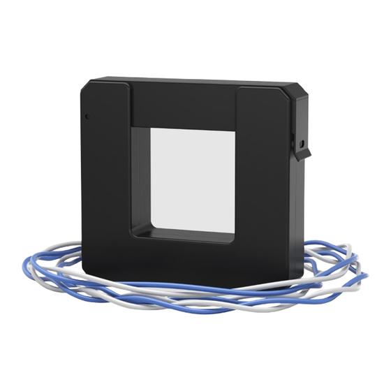
The Enphase IQ Gateway Commercial 2 uses a set of three 600 A split-core CTs for monitoring consumption. They perform metering with an
accuracy of 2.5%. Rated at pollution degree three, you can use the CTs inside electrical equipment in residential or in harsh, industrial conditions.
Read and follow all warnings and instructions in this instruction and the Quick Install Guide included with your IQ Gateway Commercial 2 and
available at https://enphase.com/contact/support.
SAFETY
SAFETY AND ADVISORY SYMBOLS
+
DANGER: This indicates a hazardous situation, which if not
avoided, will result in death or serious injury.
✓
NOTE: This indicates information particularly important for opti-
mal system operation. Follow instructions carefully.
SAFETY INSTRUCTIONS
DANGER: To reduce the risk of electric shock, always open or
+
disconnect the circuit from the power-distribution system (or
service) of the building before installing or servicing the current
transformers.
DANGER: Risk of electrocution! Do not install CTs when current
+
is flowing in the sensed circuit. Always install CT wires in the
terminal blocks before energizing the sensed circuit.
DANGER: If equipment is used in a manner not specified by
+
Enphase Energy, the protection provided by the equipment may
be impaired.
DANGER: Risk of electric shock. Be aware that installation of this
+
equipment includes the risk of electric shock. If the subpanel
cannot be de-energized, a qualified electrician can safely install
the CTs as directed by connecting the leads first and then placing
the CTs around each wire and latch.
DANGER: Risk of electric shock. Risk of fire. Only qualified per-
+
sonnel should troubleshoot, install, or replace the CTs.
✓
NOTE: Because of variances in switchboard design and main pow-
er feed, there may not always be enough space to install CTs.
✓
NOTE: Do not install the CTs in a switchboard where they exceed
75% of the wiring space of any cross-sectional area within the
equipment.
✓
NOTE: Perform all electrical installations in accordance with all
national and local electrical codes.
✓
NOTE: Restrict installation of current transformers in an area
where they would block ventilation openings, or in the area of
breaker arc venting.
✓
NOTE: Not suitable for Class 2 wiring methods and not intended
for connection to Class 2 equipment.
✓
NOTE: Secure current transformer and route conductors so that
they do not directly contact live terminals or bus.
✓
NOTE: When wiring the IQ Gateway Commercial 2 for production
and consumption metering, be sure to install the current trans-
formers (CTs) exactly as described for your application.
✓
NOTE: When installing CTs, it is important to match CT and sense
voltage phases. Be sure to consistently identify the two AC lines
at three points: the main load center feed, the IQ Gateway Com-
mercial 2, and the solar production circuit breaker. Wire colors
(typically black and red) may not always consistently identify L1
and L2. If in doubt, use a multimeter to check.
✓
NOTE: Only run active conductors through the CT. The CT can
monitor multiple active conductors. You may run more than one
wire through the CT if all wires are in the same phase and they fit
the opening in the CT.
✓
NOTE: For indoor use only.
(Model: CT-600-SPLIT)
SPECIFICATIONS
SPECIFICATION
Current transformer type
Current transformer accuracy
(error rate)
Maximum primary current
Turns ratio
Pollution degree
Dimesnions (inches)
Aperture (inches)
Supported cable size
(maximum)
Primary voltage (range)
Frequency
Operating temperature
Humidity
Compliance
UL2808 certified with service entrance
rating, RoHS (latest version)
INSTALLATION
Preparation
A ) If not already done, de-energize the
home load panel and the PV system.
Remove any pre-installed
Consumption CTs
A ) Remove the line 1, line 2, and line 3
conductors circuit to which the Consumption CTs are connected.
B ) Remove the existing CTs.
Install the Consumption CTs
A ) Refer to the diagram on the reverse of this document for wiring.
B ) Install the Consumption CTs on active phases as required:
Locate the arrow on the CT label.
•
Make sure the AC mains wire(s) are de-energized until you have
•
secured the CT wires in the terminal blocks.
To monitor consumption on Line 1:
Connect the white wire to the white "C1" and the blue wire to the
-
blue "C1" terminal.
Clamp the CT on the main supply Line 1. When the Consumption
-
CT is on the Line 1 conductor, the arrow must point toward the
load (away from the grid).
To monitor consumption on Line 2:
•
Connect the white wire to the white "C2" terminal and the blue
-
wire to the blue "C2" terminal.
Clamp the CT on the main supply Line 2. When the Consumption
-
CT is on the Line 2 conductor, the arrow must point toward the
load (away from the grid).
To monitor consumption on Line 3:
•
Connect the white wire to the white "C3" terminal and the blue
-
wire to the blue "C3" terminal.
Clamp the CT on the main supply Line 3. When the Consumption
-
CT is on the Line 3 conductor, the arrow must point toward the
load (away from the grid).
Tighten all connections to 5 in-lbs (0.6 N m).
•
C ) Close and secure the terminal block door of the
Commercial 2
.
D ) Turn on the PV system.
CT-600-SPLIT
Split core
<2.5%
600 A
4800
3
3.68 × 4.4 × 0.98
1.97 × 1.97
Up to 300 KCMIL conductors
250 VAC max
50–60 Hz
−40°C to 85°C
95%
U80002
YYWW FALCO
POLLUTION DEGREE 3
IQ Gateway
Advertisement

Related Manuals for enphase CT-600-SPLIT


Summary of Contents for enphase CT-600-SPLIT
- Page 1 Use this instruction with the Enphase IQ Gateway Commercial 2 Quick Install Guide to install consumption monitoring current transformers (CTs). The Enphase IQ Gateway Commercial 2 uses a set of three 600 A split-core CTs for monitoring consumption. They perform metering with an accuracy of 2.5%.
- Page 2 Enphase customer support: enphase.com/en-us/support/contact INSTALLATION TIPS Installing multiple conductors in a single CT If you need to install multiple conductors in a single CT, you must ensure that the conductors terminate on the same line conductor, so the voltage at the terminals of the two conductors will be zero volts between them.
- Page 3 Updated the document for product names and editorial changes. Previous releases © 2023 Enphase Energy. All rights reserved. Enphase, the e and CC logos, IQ, and certain other marks listed at https://enphase.com/trademark-usage-guidelines are trademarks of Enphase Energy, Inc. in the US and other countries.
Need help?
Do you have a question about the CT-600-SPLIT and is the answer not in the manual?
Questions and answers