Advertisement
Available languages
Available languages
Quick Links
Advertisement

Subscribe to Our Youtube Channel
Related Manuals for LaserPecker 4


Summary of Contents for LaserPecker 4
- Page 1 LaserPecker 4 Rotary Extension User Manual...
- Page 2 English Deutsch español Français 日本語 한국인 中文繁體 中文简体...
- Page 3 Jaw * 3 Jaw * 3 Technical support for this product is available globally. Please contact us if you encounter any problem with your LaserPecker 4 and we will get back to you as soon as possible. Email:support@laserpecker.com Rotary Head *1...
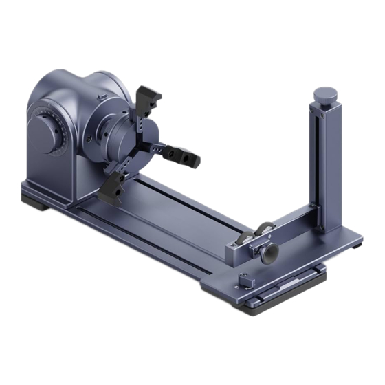
- Page 4 Component Overview & Descriptions Lever Lock Button LED Indicator USB-C Power Input Materiat Grip USB-A Power Output Angle Adjustment Knob...
- Page 5 Component Overview & Descriptions USB Output Port for Accessory DC Power Cable Input USB Output Port for Safety Shield Rotary Extension USB-C Power Input Electric Stand USB-C Power Input Rotary Extension USB-C Power Output *If the cable of the electric stand is connected to the accessory output port, the lifting button in the APP will not be able to control the electric stand, and the user needs to manually adjust the lifting button of the host to adjust the height.
-
Page 6: Quick Installation
Quick Installation Assemble the Riser Add-on Tighten the two screws to assemble Riser Add-on between LaserPecker 4 Laser Unit and Electric Stand. *Make sure the Safety Shield is assembled before this step.For details, please refer to LaserPecker 4 User Manual. - Page 7 Quick Installation Assemble the Rotary Extension Attach Rotary Head to Base Plate with 4 pcs of M3x10 screws and the Hex Key.
- Page 8 Quick Installation Jaw/stud Assembly ➀Double-step Jaws Installation Attach three double-step jaws to the rotary chuck using the wrench and 6 pcs of M3x6 screws. Tightening screws...
- Page 9 ➁Single-step Jaws Installation Attach three single-step jaws to the rotary chuck using the wrench and 6 pcs of M3x6 screws. Tightening screws...
- Page 10 ➂ Stud Component Installation Attach three stud components to the rotary chuck.
- Page 11 Quick Installation Rotary Extension Assembly Turn the Lever Slide the Tailstock onto the track along the base of the Rotary Head...
- Page 12 Quick Installation Stabilize the Rotary Extension Put the Elevation Pad under the Rotary Head to make it more table.
- Page 13 Quick Start Guide Turn on Mode Settings>Rotary Extension on the app, adjust the height and angle of the rotary. Choose an image, set its size and position, start previewing, set the engraving power and depth parameters, and start engraving. Turn on the Rotary Extension button. Turn the screw at the top of the Tailstock to adjust the height of the support bracket.
- Page 14 Quick Start Guide When the object is too large, press down When the object is fixed, press up the Lock the Lock Button and turn the gear on the Button so the chuck will rotate as it should chuck till the jaws can hold the object. when previewing and engraving/cutting.
-
Page 15: Product Specification
Product Specification Size 308*108*99mm Weight 1.7kg Chuck diameter range 52mm-80mm Engraving maximum diameter 200mm Appearance Anodic oxidation of aluminum alloy Engraving diameter range 66mm-145mm (Single -step Jaw) Engraving diameter range 0mm-128mm (Double-step Jaw) Engraving diameter range 13mm- 78mm (Stud Component) Operating system Support iOS 9.0+,Android 6.0+,MacOS 10+,Windows 10+ Power input... -
Page 16: Liste Des Accessoires
Email:support@laserpecker.com Axe du support Accessoires Tel: +86 0755-28913864 rotatif*1 d'élévation du support électrique *1 Facebook:LaserPecker 4 Support de Coussin Câble de données *1 positionnement *1 d'élévation*1 LaserPecker 4 VIP Group M3x6 Vis *6 M3x10 Vis *4... - Page 17 Indication et installation du produit Lever Lock Button LED Indicator USB-C Power Input Materiat Grip USB-A Power Output/Input Angle Adjustment Knob...
- Page 18 Indication et installation du produit Connexion support rotatif Entrée câble d'alimentation DC Ventilateur avec couvercle de protection Connexion LaserPecker 4 Port d'alimentation du support électrique Connexion support électrique * Si le câble de connexion de support électrique est connecté au port de sortie de l'accessoire, les touches d'élévation dans l'application ne seront pas en mesure de contrôler le support électrique, l'utilisateur doit ajuster manuellement les touches...
-
Page 19: Instalación Rápida
Ajusta los dos tornillos firmemente para conectar el accesorio de elevación del soporte eléctrico con la unidad principal LaserPecker 4 y el soporte eléctrico. *Primero, conecta el ventilador de la cubierta protectora de manera adecuada. El manual de instrucciones del... - Page 20 Instalación rápida Installation de l'âxe du support rotatif Fixez l'âxe de rotation à la plaque inférieure du support rotatif à l'aide de 4 vis M3x10.
- Page 21 Instalación rápida Installation de la mâchoire ➀Installation des mâchoires à deux pas Fixez les trois mâchoires à deux pas sur le mandrin rotatif avec 6 vis M3x6. Serrez les vis...
- Page 22 ➁Installation de la mâchoire à un pas Fixez les trois mâchoires à un pas sur le mandrin rotatif avec 6 vis M3x6. Serrez les vis...
- Page 23 ➂ Installation des composants du goujon Fixez les trois composant du goujon au mandrin rotatif...
- Page 24 Führen Sie die Positioniervorrichtung in die Schiene ein und schrauben Sie den Stützschalter fest. Die Positionierungsvorrichtung der Rotationsachse wird entlang der Grundplattenschiene in die Grundplatte geschoben. Drehen Sie den Stützschalter fest...
- Page 25 Stabilisez l'âxe de rotation Placez le coussin d'élévation sous le support rotatif pour la maintenir à niveau et équilibrée sur la plaque inférieure.
- Page 26 Utilisation rapide Sélectionnez l'âxe de rotation dans le réglage du mode, réglez la hauteur et l'angle, prévisualisez la taille et la position de la gravure, réglez les paramètres de puissance et de profondeur de la gravure, et démarrez la gravure. Sélectionnez l'âxe de rotation Tournez le bouton du support de positionnement pour régler la hauteur.
- Page 27 Utilisation rapide Lorsque le diamètre de l'objet sculpté Une fois le matériau de gravure fixé, vous est trop grand, appuyez sur la touche de devez relâcher la touche de verrouillage, verrouillage et tournez le mandrin pour sinon l'âxe de rotation ne tournera pas ajuster la mâchoire à...
- Page 28 Spécification du produit Taille 308*108*99mm Poids 1.7kg Gamme de diamètre de mandrin 52mm-80mm Diamètre maximum de gravure 200mm Apparence Anodisation en alliage d'aluminium Plage de diamètre de gravure 66mm-145mm (Mâchoire à un pas) Plage de diamètre de gravure 0mm-128mm (Mâchoire à deux pas) Plage de diamètre de gravure 13mm- 78mm (Composant du goujon)
Need help?
Do you have a question about the 4 and is the answer not in the manual?
Questions and answers