Advertisement
Quick Links
Advertisement

Subscribe to Our Youtube Channel
Related Manuals for LaserPecker 4


Summary of Contents for LaserPecker 4
- Page 1 LaserPecker 4 Rotary Extension User Manual...
- Page 2 此页不印刷内容...
-
Page 3: After-Sales Services
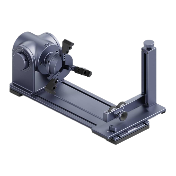
Technical support for this product is available globally. Jaw * 3 Jaw * 3 Component * 3 Please contact us if you encounter any problem with your LaserPecker 4 and we will get back to you as soon as possible. Email:support@laserpecker.com Rotary Headstock Head Online User Community LaserPecker’s... - Page 4 Component Overview & Descriptions Tailstock Stand Knob Lock key LED Indicator Ball Holder USB-A Power Output/Input Angle Adjustment Knob...
- Page 5 Component Overview & Descriptions USB Output Port for Rotary Extension USB Output Port for Safety Shield DC Power Cable Input Rotary Extension USB-A Power Input/Output Electric Stand USB-C Power Input *If the cable of the electric stand is connected to the accessory output port, the lifting button in the APP will not be able to control the electric stand, and the user needs to manually adjust the lifting button of the host to adjust the height.
-
Page 6: Quick Installation
Quick Installation Assemble the Riser Add-on Tighten the two screws to assemble Riser Add-on between LaserPecker 4 Laser Unit and Electric Stand. *Make sure the Safety Shield is assembled before this step.For details, please refer to LaserPecker 4 User Manual. - Page 7 Assemble the Rotary Headstock Attach Rotary Headstock Head to Headstock Baseplate with 4 pcs of M3x10 screws and the Hex Key.
- Page 8 Headstock Assembly ①Double-step Jaws Installation Attach three double-step jaws to the rotary chuck using the wrench and 6 pcs of M3x6 screws. Tightening screws...
- Page 9 ②Single-step Jaws Installation Attach three single-step jaws to the rotary chuck using the wrench and 6 pcs of M3x6 screws. Tightening screws...
- Page 10 ③ Stud Component Installation Attach three stud components to the rotary chuck. Tightening screws...
- Page 11 Rotary Extension Assembly Lock the tailstock stand knob Slide the tailstock into the base of the headstock along the track...
- Page 12 Stabilize the Rotary Extension Put the Elevation Pad under the Rotary Headstock to make it more table.
- Page 13 Quick Start Guide Turn on Mode Settings>Rotary Extension on the app, adjust the height and angle of the rotary. Choose an image, set its size and position, start previewing, set the engraving power and depth parameters, and start engraving. Turn on the Rotary Extension button. Turn the knob on the tailstock stand clockwise or counterclockwise to adjust height.
- Page 14 When the diameter of the carved object is After the engraving material is fixed, the lock key too large, press the lock key.Turn the chuck needs to be released, Otherwise, the Rotary to adjust the gripper to the appropriate size. Extension will not turn properly when previewing the engraving.
-
Page 15: Product Specification
Product Specification Size 308*108*99mm Weight 1.7kg Chuck diameter range 52mm-80mm Engraving maximum diameter 200mm Appearance Anodic oxidation of aluminum alloy Engraving diameter range 0mm-128mm (Double-step Jaw) Engraving diameter range 66mm-145mm (Single -step Jaw) Engraving diameter range 13mm- 78mm (Stud Component) Operating system Support iOS 9.0+,Android 6.0+,MacOS 10+,Windows 10+ Power input... - Page 16 Shenzhen Hingin Technology Co., Ltd We support global online technical support services for this product. If you have any problems during your use, please contact us. Email: support@laserpecker.com...
Need help?
Do you have a question about the 4 and is the answer not in the manual?
Questions and answers