
Related Manuals for Case IH TIGER-MATE 255


Summary of Contents for Case IH TIGER-MATE 255
- Page 1 INSTALLATION INSTRUCTIONS 90389630 TIGER-MATE® 255 FLOATING HITCH MAIN FRAME TURNBUCKLE REPLACEMENT APPROXIMATE INSTALLATION TIME: 0.5 hours Goo - 90389803 Issue date June 2022...
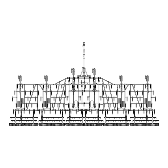
- Page 2 90389630 - TIGER-MATE® 255 FLOATING HITCH MAIN FRAME TURNBUCKLE REPLACEMENT CASE IH Tiger-Mate® 255 TM255 Double Fold Tiger-Mate® 255 TM255 Double Fold Tiger-Mate® 255 TM255 Double Fold Floating Hitch 37.4FT [YHD082923 - Floating Hitch 46.0FT [YGD082568 - Floating Hitch 55.8FT [YGD083156 -...
-
Page 3: Table Of Contents
Contents 1 SAFETY INFORMATION Personal safety ................1-1 General information and safety. -
Page 5: Safety Information
1 - SAFETY INFORMATION 1 - SAFETY INFORMATION###_2_### Personal safety Personal safety This is the safety alert symbol. It is used to alert you to potential personal injury hazards. Obey all safety messages that follow this symbol to avoid possible death or injury. Throughout this manual you will find the signal words DANGER, WARNING, and CAUTION followed by special in- structions. -
Page 6: General Information And Safety
1 - SAFETY INFORMATION General information and safety Setup safety To prevent personal injury, follow the safety messages that are on this page. Also, read the Safety Section in the front of the Operator’s Manual. DANGER Crushing hazard! Read all unpacking instructions before removing components from the shipping packages. Place each shipping package on a clean, hard, level surface prior to unpacking. -
Page 7: Kit Content
2 - KIT CONTENT 2 - KIT CONTENT Kit overview SAIS22TIL0350FA Kit 90789630 Reference Description Quantity Part Number Main frame gauge wheel turnbuckle assembly 51634324 3/8 x 2 in slotted spring pin 86624061 1-1/4 x 6-1/2 in pin 51666120 1.281X2X0.06 in washer 87613235 Adjustment wrench 51666566... - Page 8 2 - KIT CONTENT...
-
Page 9: General Information
3 - GENERAL INFORMATION 3 - GENERAL INFORMATION###_1_### Machine orientation SAVM22TIL0349FA 10.7 m (35.2 ft) implement shown Description Reference Left-hand side of the implement Front of the implement Right-hand side of the implement Rear of the implement The left-hand (1), the front (2) the right-hand (3), and the rear (4) of the implement are determined by standing behind the implement facing in the direction of travel. - Page 10 3 - GENERAL INFORMATION...
-
Page 11: Pre-Assembly
4 - PRE-ASSEMBLY 4 - PRE-ASSEMBLY PREPARING FOR ASSEMBLY Before you begin 1. Read, understand, and follow all of the safety mes- sages in the operator’s manual for the implement and those contained within this instruction sheet. 2. Service the implement on a firm, level surface. 3. -
Page 12: Turnbuckle Removal
4 - PRE-ASSEMBLY Turnbuckle removal GOIL16TIL0090FA Reference Description Rocker pivot 3/8 x 2 in slotted spring pin Washer 1-1/4 x 6 in pin Main frame gauge wheel turnbuckle assembly 1-1/4 x 5-1/2 in pin Lower gauge wheel link assembly... - Page 13 4 - PRE-ASSEMBLY 1. Remove the slotted spring pin (B) and the washer (C) from the pin (D) in the rocker pivot (A). 2. Discard the slotted spring pin (B). NOTE: A new slotted spring pin is provided in the kit. 3.
- Page 14 4 - PRE-ASSEMBLY...
-
Page 15: Assembly
5 - ASSEMBLY 5 - ASSEMBLY Main frame turnbuckle installation Turnbuckle installation SAIS19TIL0763FA Reference Description Rocker pivot Washer 1-1/4 x 6 in pin Lower gauge wheel link assembly 1206.5 mm (47-1/2 in) Main frame gauge wheel turnbuckle assembly 3/8 x 2 in slotted spring pin Adjustment wrench 1.281X2X0.06 in washer 1-1/4 x 6-1/2 in pin... - Page 16 5 - ASSEMBLY 1. Adjust the initial distance (H) between the center of the turnbuckle clevises on the main frame gauge wheel turnbuckle assembly (1) to 1206.5 mm (47-1/2 in). 2. Position the main frame gauge wheel turnbuckle as- sembly (1) to the lower mount of the rocker pivot (A). NOTE: Orient the turn buckle assembly (1) with the adjust- ment decal towards the front of the implement.
- Page 17 5 - ASSEMBLY 12. Assemble the adjustment wrench (3) to the 1-1/4 x 6-1/2 in pin (5). 13. Secure the adjustment wrench (3) to the 1-1/4 x 6-1/2 in pin (5) with the klik pin (6). SAIS19TIL0812AA 14. Verify the distance (H) between the center of the turn- buckle clevises on the main frame gauge wheel turn- buckle assembly (1) is set to 1206.5 mm (47-1/2 in).
- Page 18 CNH Industrial America Goodfield Plant 600 E. Peoria Street, PO Box 65 Goodfield, Illinois USA 61742 SERVICE - Technical Publications & Tools PRINTED IN U.S.A. © 2022 CNH Industrial America LLC. All rights reserved. No part of the text or illustrations of this publication may be reproduced. CNH Industrial America LLC reserves the right to make improvements in design and changes in specifications at any time without notice and without incurring any obligation to install them on units previously sold.
Need help?
Do you have a question about the TIGER-MATE 255 and is the answer not in the manual?
Questions and answers