Table of Contents
Advertisement
Quick Links
Technical information
Installation instructions
Belaria
pro (24)
®
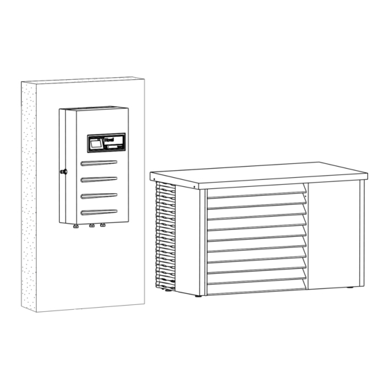
Modulating air/water heat pump
Indoor unit
Belaria
pro (24)
®
The heat pump is only allowed to be set up, installed
and taken into operation by customer service techni-
cians who have been authorised by Hoval for this pur-
pose. Electrical installations are only allowed to be car-
ried out by an electrician.
Subject to modifi cations
Outdoor unit
Inneneinheit / Ausseneinheit
THDA
01.02.2022
|
4 221 011 / 02 - 08/23
Belaria
MIBE
06.12.2019
These instructions are applicable to the
following types:
1-Belaria
pro (24)
®
EN
Advertisement
Table of Contents

Related Manuals for Hoval Belaria pro (24)


Summary of Contents for Hoval Belaria pro (24)
- Page 1 The heat pump is only allowed to be set up, installed and taken into operation by customer service techni- cians who have been authorised by Hoval for this pur- pose. Electrical installations are only allowed to be car- ried out by an electrician.
-
Page 2: Table Of Contents
TABLE OF CONTENTS Important notices System manual ..................................4 General safety instructions ..............................4 Explanation of the symbols ..............................4 1.3.1 Warnings ..................................4 1.3.2 Warning symbols................................5 1.3.3 Information ..................................5 On delivery ...................................5 Notes on the installation location ............................5 1.5.1 Installation location of the indoor unit ..........................5 1.5.2 Installation location of the outdoor unit ..........................6 Transport ....................................8... - Page 3 TABLE OF CONTENTS Safety measures relating to EMC-compliant assembly ....................41 4.4.1 Recommended cable cross-sections and maximum permitted cable lengths: ..............43 Flushing, filling and venting the heating circuit ......................44 Water quality ..................................45 4.6.1 Water quality of the heating water: ..........................45 Commissioning Prerequisites for commissioning: ............................46 Commissioning of the heat pump .............................46 5.2.1...
-
Page 4: Important Notices
Important notices System manual All instructions relevant to your system can be found in WARNING the Hoval system manual. Please retain all instructions. In exceptional cases, the instructions can be found with The heat generator can only be de-energised the components. -
Page 5: Warning Symbols
IMPORTANT NOTICES On delivery 1.3.2 Warning symbols The following warning symbols are combined with signal Carry out a visual inspection immediately on receiving the words CAUTION, WARNING and DANGER for the warn- heat pump. ing notes. If any damage is found, take the necessary steps as de- fined in the delivery contract. -
Page 6: Installation Location Of The Outdoor Unit
IMPORTANT NOTICES 1.5.2 Installation location of the outdoor unit Observe the following installation instructions. Sound emissions The outdoor unit runs exceptionally smoothly, thanks to WARNING its engineering design. Nevertheless, it is important that • The outdoor unit is only allowed to be in- the installation area is as far as possible from the living stalled and operated outdoors and must area that is sensitive to noise. - Page 7 IMPORTANT NOTICES Routing of hydraulic connection lines Frost protection • The hydraulic connection lines should be kept as short • For buildings that are not permanently occupied (e.g. as possible due to heat losses and pressure drops. vacation homes), a bivalent second heat generator •...
-
Page 8: Transport
• Failure to comply with the operating instructions • Incorrect installation • Failure to comply with the engineering guidelines • Maintenance not carried out by Hoval or by a company authorised by Hoval • Failure to comply with the specified maintenance intervals •... -
Page 9: Technical Information Description
TECHNICAl INFORMATION Technical information Description flow sensor or heat meter, the control and a 4.3” colour touch The Belaria pro (24) is a compact air/water heat pump with ® display. A sensor package with contact sensor, immersion a modulating scroll compressor and an inverter with patented sensor and outdoor sensor is included. -
Page 10: Description Of Automatic Function Device
TECHNICAl INFORMATION 2.1.1 Description of automatic function device The ingenious control program of the built-in WFA-200S heat pump automatic function device is adapted to efficient heat pump application. The entire heat pump system is activated according to requirements and is equipped with a large num- ber of monitoring, safety and reporting functions. -
Page 11: Technical Data
TECHNICAl INFORMATION Technical data Hoval Belaria pro (24) ® ® Belaria pro (24) Type pro (24) 35 °C/55 °C A+++/A+++ • Energy efficiency class of the compound system with control • Room heating energy efficiency “moderate climate” 35 °C ηS •... - Page 12 TECHNICAl INFORMATION Type pro (24) Electrical data • Electrical connection compressor V/Hz 3~400/50 • Electrical connection electric heating element V/Hz • Control electrical connection V/Hz 1~230/50 • Max. heat pump operating current 19.5 • Max. compressor operating current 17.4 • Max. electric heating element operating current •...
-
Page 13: Diagrams Of Areas Of Application
TECHNICAl INFORMATION Diagrams of areas of application 2.4.1 Heating and domestic hot water Belaria pro (24) ® Area of application of the heat pump for heating and domestic hot water Outdoor temperature (°C) Aussentemperatur (°C) 2.4.2 Cooling Belaria pro (24) ®... -
Page 14: Performance Data
TECHNICAl INFORMATION Performance data 2.5.1 Performance data heating Maximum heat output allowing for defrosting losses Belaria pro (24) ® Data according to EN 14511 Heat output - t 35 °C Coefficient of performance - t 35 °C Leistungszahl - t 35 °C Heizleistung - t 35 °C... - Page 15 TECHNICAl INFORMATION Belaria pro (24) ® Data according to EN 14511 Maximum output Minimum output °C °C 16.0 10.0 17.6 10.0 18.8 10.0 20.7 10.0 22.1 10.5 24.0 10.1 27.4 29.5 10.0 30.5 10.0 30.8 10.0 31.4 10.0 15.6 16.8 18.1 10.1 20.3...
-
Page 16: Performance Data Cooling
TECHNICAl INFORMATION 2.5.2 Performance data cooling Maximum cooling capacity Belaria pro (24) ® Cooling capacity - t 18 °C Energy efficiency ratio - t 18 °C Kühlleistung - t 18 °C Leistungszahl - t 18 °C tQ [°C] tQ [°C] [°C] [°C] Maximum output... -
Page 17: Pressure Drop Of The Hydraulic Connection Lines
TECHNICAl INFORMATION Pressure drop of the hydraulic connec- tion lines The instructions in chapter 1.5.2 must be observed for the configuration of the hydraulic connection lines. The pressure loss curves shown in the following diagram contain the sum of the pressure drops of the outdoor unit, the indoor unit and the hydraulic connection lines without bends or diversions. -
Page 18: Dimensions And Space Requirements
TECHNICAl INFORMATION Dimensions and space requirements 2.7.1 Dimensions/space required for indoor unit Hoval Belaria pro (24) indoor unit ® (Dimensions in mm) 1 Flow outdoor unit 1½″ ext. th. (return not guided through indoor unit) 2 Flow heating 1½″ ext. th. -
Page 19: Dimensions Of The Outdoor Unit
TECHNICAl INFORMATION 2.7.2 Dimensions of the outdoor unit (Dimensions in mm) Front view Front view, open View from the left View from above Suction side Exhaust side Suction side Exhaust side Condensate drain 1″ Connection hydraulic connection line return 1½″ ext. thread Connection hydraulic connection line flow 1½″... -
Page 20: Space Required For Outdoor Unit
TECHNICAl INFORMATION 2.7.3 Space required for outdoor unit (Dimensions in mm) Cascade plant Exhaust side Suction side Suction side Exhaust side In order to ensure accessibility during mainte- WARNING nance, a clearance of at least 600 mm upwards Any possible openings/sinks and ignition must be maintained. -
Page 21: Presentation Of Protection Zones
TECHNICAl INFORMATION 2.7.4 Presentation of protection zones Belaria pro with refrigerant R290 ® (Dimensions in mm) Floor plan - protection zone when installed in front of a wall Window balustrade > upper edge of heat pump Suction side Suction side Exhaust side Exhaust side View - protection zone when installed in front of a wall... - Page 22 TECHNICAl INFORMATION Floor plan flat roof - protection zone Parapet height max. 150 mm Door/window balustrade > upper edge of parapet Suction side Exhaust side • Strict compliance with safety meas- Flat roof mounting/garage ures regarding combustible refriger- ants. • All standards concerning statics, wind load and access to roofs must be Section flat roof - protection zone complied with.
-
Page 23: Installation
INSTAllATION Installation Diagram of wall penetration, ground and routing works The wall penetration should slope down from the inside to the outside. To avoid damage, the opening should be pad- ded on the inside or, for example, lined with a PVC pipe. After installation, the wall opening must be sealed with a suitable sealing compound on site in compliance with fire protection regulations! Example: Connection lines laid in the ground... -
Page 24: Installation Of Outdoor Unit
INSTAllATION Installation of outdoor unit The applicable laws, regulations and stand- § ards have to be observed, in particular EN 378 Parts 1 and 2 as well as BGR 500. 3.2.1 Installation variants and foundation dia- grams If the outdoor unit is installed at wind-prone locations, the alignment of the outdoor unit must be selected in such a way that the expected wind direction is at right angles to the suction/discharge direction. - Page 25 INSTAllATION Variant 1: Strip foundation Plan (view from above, dimensions in mm) Suction side Exhaust side Attachment of the outdoor unit from the out- side (laterally) using the supplied clamps. The clamps are visible. It is not necessary to remove the cladding sections.
- Page 26 INSTAllATION Variant 2: Floor plate Plan (view from above, dimensions in mm) Suction side Exhaust side Attachment of the outdoor unit from the out- side (laterally) using the supplied clamps. The clamps are visible. It is not necessary to remove the cladding sections.
-
Page 27: Transport
INSTAllATION 3.2.2 Transport Transport by crane NOTICE The outdoor unit can be lifted by a crane and carried to • The outdoor unit is never allowed to be tilt- the installation site. ed more than 30° during transport. For this purpose, there are three stiffening brackets be- •... -
Page 28: Mounting Outdoor Unit On Foundation
INSTAllATION 3.2.3 Mounting outdoor unit on foundation When placing the base, pay attention to the maximum length of the hydraulic connection lines. Place the outdoor unit (1, Fig. 04) on a firm surface (con- crete base (2), floor plate or similar base) on site. Please also note the “static system design”... -
Page 29: Grounding The Outdoor Unit
INSTAllATION 3.2.4 Grounding the outdoor unit If the protective earth conductor has been properly con- nected, then the inverter box (Fig. 05) is grounded. After maintenance work, make sure that the grounding is prop- erly restored. If required, external lightning protection can be attached in a 10 mm hole (Fig. -
Page 30: Making The Condensate Drain
INSTAllATION 3.2.5 Making the condensate drain Outdoor Special measures must be taken for the resulting conden- unit sate. Per defrosting cycle, up to 10 litres of condensate water can accumulate within a very short time in extreme cases. In this regard, it must always be ensured that this is properly discharged or can seep away. -
Page 31: Installation Of Indoor Unit
INSTAllATION Installation of indoor unit View from above NOTICE • When installing the indoor unit, observe the minimum clearances specified in chap- ter 2.7.1. • False flow rates as a result of false pipe- work, false fittings or improper pump oper- ation could cause damage! Fig. -
Page 32: Installation
• Install pockets to prevent single-pipe gravity circulation! Please observe the notes in the engineering documents of the responsible Hoval sales company with re- spect to the appropriate hydraulic circuits! Looking for the appropriate hydraulic schematic? Please contact your local Hoval partner. -
Page 33: Installation Of Outdoor Unit
INSTAllATION Installation of outdoor unit All pertinent laws, regulations and standards Important information for creating the hydraulic con- § for heating house pipework and for heat pump nection lines systems must be complied with, in particular • The maximum permissible length of the DN 40 lines be- EN 378 parts 1 and 2 as well as BGR 500. -
Page 34: Connection On The Heating Side
INSTAllATION 4.2.2 Connection on the heating side The connections for the heating flow and return are locat- ed on the front of the outdoor unit behind the slatted front. The connections are described in chapter 2.7. • To connect the outdoor unit hydraulically, the slatted front on the outlet side must be removed. -
Page 35: Electrical Connection
INSTAllATION 4.2.3 Electrical connection A qualified technician must install the electrical WARNING supply to the equipment. All electrical power supply circuits must be The circuit diagram is supplied separately. Re- switched off before accessing the terminals. fer to this for the conductor cross-section re- quired for the mains supply. - Page 36 INSTAllATION Connecting the outdoor unit electrically Chapter 3.1 contains an example of how the Disassemble the slatted front (1, Fig. 13) of the outdoor unit and connect the connection lines of the indoor unit electrical lines can be laid in the ground. in accordance with the included circuit diagram on the terminal box.
-
Page 37: Installation Of Indoor Unit
INSTAllATION Installation of indoor unit 4.3.2 Oxygen diffusion • In the case of underfloor heating systems without diffu- All pertinent laws, regulations and standards sion-proof plastic piping or open heating systems, cor- § for heating house pipework and for heat pump rosion of the steel parts can occur as a result of oxygen systems must be complied with. -
Page 38: Electrical Connection
INSTAllATION 4.3.4 Electrical connection A qualified technician must install the electrical WARNING supply to the equipment. All electrical power supply circuits must be The circuit diagram is supplied separately. Re- switched off before accessing the terminals. fer to this for the conductor cross-section re- quired for the mains supply. - Page 39 INSTAllATION Connecting the indoor unit electrically The incoming cables must be protected with appropriate For the electrical connection, the front cladding (1, Fig. 14) strength; see chapter 2.3. must be removed and the sheet metal cover of the terminal box opened by unscrewing the screw and swinging it open. Connection terminals: The cable introductions are located on the underside of 3-tiered:...
-
Page 40: Control Set For External Electric Heating Element
INSTAllATION 4.3.5 Control set for external electric heating element The indoor unit does not have an electric heating element as standard. When using an externally installed electric heating element, a control set is required for its control, which is installed in the indoor unit. The control set includes a contactor, terminal blocks and is pre-wired at the factory. -
Page 41: Safety Measures Relating To Emc-Compliant Assembly
INSTAllATION Safety measures relating to EMC-com- • Measures must be taken in the building and on electri- cal equipment to protect the units against overvoltage pliant assembly caused by lightning strikes. • The mains connection for the heating system must be •... - Page 42 INSTAllATION In the case of star-shaped data bus networks, double To ensure correct electrical installation, unit connec- tion and equipotential bonding (energy supply com- earthing is not permitted. The earthing must be carried out on one side at the star point. pany and building installation), all applicable laws, regulations and standards must be complied with;...
-
Page 43: Recommended Cable Cross-Sections And Maximum Permitted Cable Lengths
INSTAllATION 4.4.1 Recommended cable cross-sections and maximum permitted cable lengths: Line type Cross-section Length Power supply of the heat See wiring diagram unlimited generator (230 V/400 V) Cables carrying mains See wiring diagram unlimited voltages from actuators Cables carrying low volt- min. -
Page 44: Flushing, Filling And Venting The Heating Circuit
INSTAllATION Flushing, filling and venting the heating circuit The system must be absolutely free of air be- fore commissioning. NOTICE Before flushing, make sure that the built-in circulating pump is flushed in the prescribed direction to avoid damage to the circulating pump. -
Page 45: Water Quality
8.3 and 9.0. In particular, the following specifi cations must be com- plied with: • Hoval heat generators are suitable for heating systems Filling and replacement water without signifi cant oxygen intake (system type I in ac- •... -
Page 46: Commissioning
COMMISSIONING Commissioning Commissioning of the heat pump Commissioning may only be performed by Hoval Service • The TopTronic E controller module should ® or a trained specialist authorised by Hoval. be configured by a specialist authorised by Hoval (commissioning assistant). -
Page 47: Setting The Relief Valve With Modular Storage Tank
COMMISSIONING Monitoring work before handover to the operator Proceed as follows for commissioning: Before the heat generator is handed over to the operator, 1. Carry out the parameter settings according to the all commissioning or maintenance work must have been system diagram. -
Page 48: Manual Operation
COMMISSIONING 5.4.1 Manual operation This chapter is exclusively intended to describe the function of the manual operation settings. All other control elements of the control unit are described in the operating instructions. CAUTION Scalding hazard due to hot water tempe rature, since the hot water temperature can exceed the tempera- ture setpoint! Manual operation Settings under:... -
Page 49: Maintenance
We our service representative. therefore recommend that you conclude a service con- tract with your Hoval customer service department for this purpose. Indoor unit If necessary, the indoor unit and the outdoor unit can be The work described below is normally performed by the cleaned with a damp cloth. -
Page 50: Cleaning The Condenser
MAINTENANCE 6.3.2 Cleaning the condenser Proceed as follows to clean the evaporator and the Set the blocking switch to “0” (1, Fig. 19) and disconnect condensate drip tray: the heat generator from the mains (main switch, fuse). 1. Remove the cover (1, Fig. 17) of the outdoor unit by removing two screws (2) each on left and right. -
Page 51: Cleaning And Servicing The Strainer
MAINTENANCE 6.3.3 Cleaning and servicing the strainer A filter ball valve (strainer) (3, Fig. 20) is installed in the return of the outdoor unit, which is located at the bottom right, directly in front of the lead-through into the refriger- ation section. -
Page 52: Cleaning And Servicing The Sludge Separator
MAINTENANCE 6.3.4 Cleaning and servicing the sludge separator If the differential pressure is 0.3 bar or more, the filter cartridge must be cleaned. The first check should be carried out during commission- ing, subsequent checks depend on the degree of contam- ination in the system, but should be carried out at least every 6 months. -
Page 53: Decommissioning And Storage
If the outdoor unit was damaged during • How, if necessary, a heat pump that is not needed for transport or storage, contact Hoval customer service the moment should be stored immediately. They must carry out a leak test with a suit- able leak detector. -
Page 54: Disposal
The refrigerant is only allowed to be drawn off and disposed of in accordance with the relevant regulations by an authorised Hoval customer service technician. Failure to effect proper disposal can lead to damage to the en- vironment and health. -
Page 55: Appendix
• Any person performing work on the refrig- than once. If the failure indication lamp contin- eration circuit must have a certificate of ues to be lit, please contact Hoval Customer competence in handling flammable refrig- Service. erants or be supervised by such a person. - Page 56 4 221 011 / 02...
- Page 57 4 221 011 / 02...
- Page 58 COPY FOR PLANT USER Confirmation The user (owner) of the system herewith confi rms that • he has received adequate instruction in the operating and maintenance of the installation, • received and taken note of the operating and maintenance instructions and, where applicable other documents con- cerning the installation and any further components.
Need help?
Do you have a question about the Belaria pro (24) and is the answer not in the manual?
Questions and answers