urmet domus VOG 5W 1760 Installation Handbook
2voice hands-free wifi video door phone
Hide thumbs
Also See for VOG 5W 1760:
- Configuration booklet (104 pages) ,
- Manual (68 pages) ,
- Quick manual for use (40 pages)
Table of Contents
Advertisement
Available languages
Available languages
Quick Links
Advertisement
Table of Contents

Related Manuals for urmet domus VOG 5W 1760


Summary of Contents for urmet domus VOG 5W 1760
- Page 1 Mod. 1760 DS1760-043C LBT21224 VIDEOCITOFONO 2VOICE VIVAVOCE WiFi 2VOICE HANDS-FREE WIFI VIDEO DOOR PHONE Interactive Links LINKLINKLINKLINK Sch./Ref. 1760/15 (nero / black) Sch./Ref. 1760/16 (bianco / white) LIBRETTO DI INSTALLAZIONE INSTALLATION HANDBOOK...
-
Page 2: Table Of Contents
Interactive Links Nel documento sono presenti LINK INTERATTIVI per rendere la consultazione più rapida ed efficiente. ITALIANO INDICE 1. DESCRIZIONE GENERALE ........................3 2. DESCRIZIONE DEI COMPONENTI E CARATTERISTICHE ............... 3 3. INSTALLAZIONE ............................5 3.1. DESCRIZIONE DEI MORSETTI ......................6 3.2. -
Page 3: Descrizione Generale
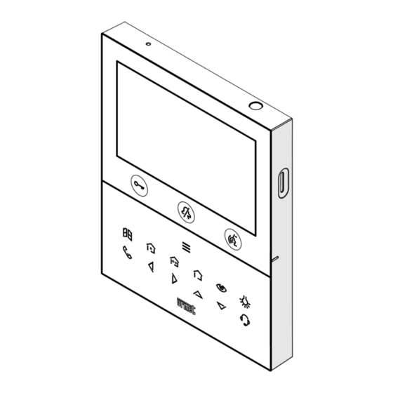
ITALIANO DESCRIZIONE GENERALE I videocitofoni Sch. 1760/15 e Sch. 1760/16 sono dedicati all’utilizzo in impianti videocitofonici del sistema 2Voice. Le caratteristiche principali sono: • schermo a colori TFT-LCD da 5’’ (Wide Angle); • pulsanti soft-touch retroilluminati (*); • possibilità di attivazioni delle funzioni del videocitofono tramite comandi gestuali sul sensore IR o tramite comandi vocali (di default disabilitate);... - Page 4 : tasto attivazione comando Yokis 2 e nello stesso tempo chiusura del contatto presente tra i morsetti Y1 e Y2 (max 50 mA @ 24 V ) : tasto menu pulsanti Yokis : tasto autoinserzione / palleggiamento video : tasto funzione speciale : tasto chiamata intercomunicante : tasto freccia scorrimento verso sinistra : tasto freccia scorrimento verso destra...
-
Page 5: Installazione
INSTALLAZIONE ATTENZIONE! Per un corretto funzionamento dei comandi gestuali (Gesture), non installare il dispositivo in luoghi in cui può essere esposto direttamente ai raggi solari, in quanto il sensore IR è sensibile alla luce. • Murare la scatola incasso Mod. 503 o la scatola a incasso Ø 60 all’altezza indicata nel disegno seguente. La scatola a incasso Mod. 503 può essere installata sia in orizzontale che in verticale. -
Page 6: Descrizione Dei Morsetti
3.1. DESCRIZIONE DEI MORSETTI Morsettiera sinistra Morsetti per alimentatore locale Sch. 1723/22 Negativo per suoneria supplementare Positivo per suoneria supplementare Pulsante Pulsante Morsettiera destra Chiamata al piano PANIC Allarme panico LINE OUT Uscita BUS alimentazione LINE IN Ingresso BUS alimentazione 3.2. -
Page 7: Prestazioni Del Videocitofono In Base Alla Modalità Di Configurazione
JUMPER (JP3) Il seguente Jumper permette la regolazione della terminazione di linea (Z) nel caso di collegamento del videocitofono in entra-esci. La terminazione di linea deve essere inserita sull’ultimo videocitofono. Terminazione inserita (default) Terminazione non inserita Per la posizione dei jumper JP1 e JP2 e del dip-switch SW1 n.1 fare riferimento al capitolo successivo del seguente libretto. -
Page 8: Vincoli Installativi Del Videocitofono
Temporizzazione Non disponibile Non disponibile Disponibile apriporta automatico Visualizzazione delle schermate durante le chiamate Non disponibile Non disponibile Disponibile intercomunicante e al centralino Comandi vocali Non disponibile Non disponibile Disponibile Accensione contemporanea di tutti i videocitofoni Non disponibile Non disponibile Disponibile (#) alla ricezione di una chiamata... -
Page 9: Inserimento Contatti Per Chiamate Intercomunicanti
“Limite numero di Per il numero massimo di videocitofoni o per altre tipologie di cavi, vedere il libretto videocitofoni in colonna montante DS1760-026” sul sito Urmet scansionando il seguente QR Code. Se il videocitofono Sch. 1760/15 o /16 viene installato come ricambio in sostituzione ad un altro videocitofono è necessario che venga alimentato tramite l’alimentatore locale e configurato con la modalità di utilizzo Alimentatore locale. - Page 10 • Nel menu di configurazione premere il tasto fino a selezionare la voce “Contatti”. • Premere il tasto per confermare la selezione. • Per inserire un nuovo contatto premere il tasto e selezionare l’icona di aggiunta nuovo contatto • Premere il tasto per confermare e visualizzare sul display la seguente schermata: •...
- Page 11 • Contatto esterno: chiamata a un videocitofono presente in un altro appartamento ma all’interno della stessa colonna videocitofonica • Contatto interno: chiamata a un videocitofono presente nello stesso appartamento Codice ID del videocitofono Premere il tasto per selezionare la seguente icona , successivamente premere il tasto inserire il codice ID del videocitofono.
-
Page 12: Ripristino Ai Parametri Di Fabbrica
• Premere il tasto per salvare il contatto in rubrica. Premere il tasto per annullare e ritornare alla pagina dei contatti. 7. RIPRISTINO AI PARAMETRI DI FABBRICA Per ripristinare il dispositivo ai parametri di fabbrica seguire la seguente procedura: • Premere 2 volte il tasto quando il videocitofono è... - Page 13 • Il display visualizza la seguente schermata: Premendo i tasti è possibile selezionare quali parametri del videocitofono si desidera riportare ai valori di fabbrica. Dopo aver effettuato la selezione premere il tasto per abilitare o disabilitare il parametro al ripristino ai dati di fabbrica. L’abilitazione è confermata dalla presenza dell’icona di fianco al nome del parametro.
-
Page 14: Caratteristiche Tecniche
CARATTERISTICHE TECNICHE Tensione di alimentazione (LINE IN): ....................36 ÷ 48 V Tensione di alimentazione (V+; V-): ......................24 V~ Assorbimento (LINE IN): ........................@ 48 V Riposo: ............................. < 3 mA A regime: ..........................< 160 mAcc Assorbimento (V+; V-): ........................@ 24 V~ Riposo: ............................ -
Page 15: English
ENGLISH INDEX 1. GENERAL DESCRIPTION ........................16 2. DESCRIPTION OF COMPONENTS AND FEATURES ................16 INSTALLATION............................18 3.1. TERMINAL DESCRIPTION ......................19 3.2. JUMPER AND DIP-SWITCH SW1 NO.1 (DEFAULT) ..............19 4. VIDEO DOOR PHONE PERFORMANCE ACCORDING TO CONFIGURATION METHOD ...... - Page 16 ENGLISH GENERAL DESCRIPTION The video door phones Ref. 1760/15 and Ref. 1760/16 are dedicated to use in 2Voice video door phone systems. The main features are: • colour 5’’ TFT-LCD screen (Wide Angle); • backlit soft-touch buttons (*); • possibility of activating video door phone functions via gesture commands on the IR detector or via vocal commands (disabled by default);...
- Page 17 Yokis 1 command setting key and closing, at the same time, of the contact between terminals Y1 and Y2 (max. 50 mA @ 24 V ) : Yokis key menu key : auto-on / video switching key : special function key : intercom call key : left scrolling arrow key : right scrolling arrow key...
- Page 18 INSTALLATION ATTENTION! For proper operation of the Gesture commands, do not install the device in places where it may be exposed to direct sunlight, as the IR detector is sensitive to light. • Install the flush-mounting box Mod. 503 or the flush-mounting box Ø 60 at the height indicated in the following drawing. The flush-mounting box Mod. 503 can be horizontally or vertically installed. • Fix the bracket to the mounting box as indicated. • Program the dip-switches and connect the system wires to the terminal boards.
- Page 19 3.1. TERMINAL DESCRIPTION Left terminal board Terminals for local power supply unit Ref. 1723/22 Negative for additional chime Positive for additional chime Button Button Right terminal board Floor call PANIC Panic alarm LINE OUT Power supply BUS output LINE IN Power supply BUS input 3.2.
- Page 20 JUMPER (JP3) The following Jumper allows to adjust the line termination (Z) in case of in-out video door phone connection. The line termination must be inserted into the last video door phone. Termination inserted (default) Termination not inserted For position of jumpers JP1 and JP2 and dip-switch SW1 no.1 refer to the next chapter of the following handbook.
- Page 21 Automatic door opener Not available Available Available timing Screen displaying during intercom Not available Not available Available and switchboard calls Vocal commands Not available Not available Available Simultaneous ignition of all video door Not available Not available Available (#) phones when a call is received.
- Page 22 For the maximum number of video door phone or for other types of cables, see the booklet “Limit number video door phones in riser DS1760-026” on the Urmet website by scanning the following QR Code. If the video door phone Ref. 1760/15 or /16 is installed as a spare to replace a video door phone, it must be powered through the local power supply and configured with the local power mode of use. 6. CONTACT INSERTION FOR INTERCOM CALLS In order to make intercom calls, it is necessary to enter contacts in the video door phone directory.
- Page 23 • The display shows the following screen: • In the configuration menu press the key until selecting “Contacts”. • Press the key to confirm the selection. • To enter an new contact, press the key and select the icon to add a new contact • Press the key to confirm and display the following screen: •...
- Page 24 • External contact: call to a video door phone in another apartment but within the same video door phone riser • Internal contact: call to a video door phone in the same apartment Video door phone ID code Press the key to select the following icon , then press the key to enter the video door phone...
- Page 25 • Press the key to save the contact in the book. Press the key to cancel and return to the contact page. 7. RESET TO FACTORY SETTINGS To reset the device to factory settings, proceed as follows: • Press the key twice when the video door phone is in stand-by mode to turn on the display and view the Homepage.
- Page 26 • The display shows the following screen: Press the keys to select which video door phone parameters you want to reset to factory values. When the selection has been made, press the key to enable or disable the parameter for reset to factory data. Enabling is confirmed by the presence of the icon next to the parameter name.
- Page 27 TECHNICAL SPECIFICATIONS Power voltage (LINE IN): ........................36 ÷ 48 V Power voltage (V+; V-): ..........................24 V~ Consumption (LINE IN): ........................@ 48 V Standby: ............................< 3 mA Full rate: ........................... < 160 mAcc Consumption (V+; V-): ........................@ 24 V~ Standby: ............................
- Page 28 FUNZIONE DI INOLTRO DI CHIAMATA Di seguito vengono elencate le varie azioni da eseguire per abilitare la funzione in modo facile e veloce: 1. INSTALLATORE — Configurazione e fase di test della funzione sul videocitofono per mezzo dell’App CallMe Set. — Abilitazione al funzionamento del videocitofono. 2. UTENTE — Creazione di un account per mezzo dell’App CallMe. —...
Need help?
Do you have a question about the VOG 5W 1760 and is the answer not in the manual?
Questions and answers