
Related Manuals for Omtech USB460j


Summary of Contents for Omtech USB460j
- Page 1 V20230511 USB460j Cabinet Laser Engraver User Manual Read Carefully Before Use Keep for Future Reference...
- Page 2 PREFACE Thank you for choosing our laser equipment. Your CO laser engraving machine is intended for personal and professional use. When used in accordance with these instructions, it comprises a Class 1 laser system but some components remain EXTREMELY dangerous. Never disable the preinstalled safety devices and always use your laser safely and responsibly.
-
Page 3: Table Of Contents
CONTENTS 1. Introduction ................................1 1.1 General Information ............................1 1.2 Symbol Guide..............................2 1.3 Designated Use..............................2 1.4 Technical Specifi cations ..........................3 1.5 Components..............................4 2. Safety Information ............................... 10 2.1 Disclaimer ..............................10 2.2 General Safety .............................. 10 2.3 Laser Safety ..............................11 2.4 Electrical Safety ............................12 2.5 Material Safety ..............................12 3. - Page 4 4.4.4 Function Menu .............................25 4.4.5 Z Axis ..............................25 4.4.6 U Axis ..............................25 4.4.7 Resetting the Axes..........................25 4.4.8 Laser Movement Mode ........................26 4.4.9 Laser Pulse Mode ..........................26 4.4.10 Setting the Origin ..........................27 4.4.11 Setting Default Parameters .........................28 4.4.12 Restoring Default Parameters ......................28 4.4.13 Interface Language ..........................28 4.4.14 IP Address ............................29 4.4.15 Diagnostic Tools ..........................29...
-
Page 5: Introduction
1. Introduction 1.1 General Information This manual is the designated user guide for the installation, setup, safe operation, and maintenance of your cabinet laser engraver. It is divided into six chapters covering general information, safety instructions, installation steps, operation instructions, maintenance procedures, and contact information. ALL personnel involved in the installation, setup, operation, maintenance, and repair of this machine should read and understand this manual, particularly its safety instructions. -
Page 6: Symbol Guide
1.2 Symbol Guide The following symbols are used on this machine’s labeling or in this manual: These items present a risk of serious property damage or personal injury. These items address similarly serious concerns with regard to the laser beam. These items address similarly serious concerns with regard to electrical components. -
Page 7: Technical Specifi Cations
1.4 Technical Specifi cations Model USB460j Diameter 3.15 in. 50 mm Laser Tube Length 40 in. 1000 mm Diameter 0.71 in. 18 mm Focus Lens Thickness 0.08 in. 2 mm Focal Length 2 in. 50.8 mm Diameter 0.98 in. 25 mm... -
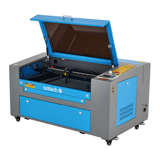
Page 8: Components
1.5 Components Main Parts Front A. Cover—The cover provides access to the main bay for placing and retrieving materials, as well as fi xing the laser path alignment and other maintenance. Power to the laser is automatically cut when the cover is opened. B. - Page 9 Left A. Left Access Door—This door provides access to the air compressor, as well as the main bay for work on the mirrors and Y-axis rail. Its interlock automatically pauses work if the door is opened. B. Exhaust Fan—This fan pulls out gases and airborne debris from the worktable, sending it through your vent to a window or air purifi...
- Page 10 Laser Path A. Laser Tube—This CO₂-fi lled glass tube is mounted D. 3rd Mirror—This adjustable-angle mirror moves on brackets and immobile. Its connection to the with the laser head to allow the laser beam to travel laser power supply is extremely high voltage and along the X axis.
- Page 11 Connection Inputs A. USB Port—This port allows you to load and save designs and parameters directly onto the engraver. B. USB Line Port—This port connects to your control computer and its engraving software using any of its USB ports. C. Ethernet Port—This port connects to your control computer and its software either directly or via the internet.
- Page 12 Control Console Returns the machine to the saved Sets the minimum laser power of the default parameters. current running layer. Sets the starting point for the laser Starts or pauses the work. head. Moves the X axis or the left/right cursor. Moves the Z or U axis if Z Move or U Manually fi...
- Page 13 Console Screen A. Graphic Display Area: Traces the processed fi le image during fi le preview display and processing. B. Parameter Display Area: Displays the fi le number, speed, and maximum power of the current processing fi le. C. Coordinate Display Area: Displays the coordinate values of the current position of the laser head. D.
-
Page 14: Safety Information
2. Safety Information 2.1 Disclaimer Your engraver may diff er somewhat from those shown in this manual due to options, updates, etc. Please contact us if your engraving machine came with an outdated manual or if you have any other questions. 2.2 General Safety Instructions •... -
Page 15: Laser Safety
2.3 Laser Safety Instructions When used as instructed, this machine comprises a Class 1 laser system safe for users and bystanders. However the invisible engraving laser, the laser tube, and its electrical connections remain EXTREMELY dangerous. Used or modifi ed without care, they can cause serious property damage and personal injury including but not limited to the following: •... -
Page 16: Electrical Safety
2.4 Electrical Safety Instructions • ONLY use this device with a compatible and stable power supply with less than 5% fl uctuation in its voltage. • DO NOT connect other devices to the same fuse, as the laser system will require its full amperage. Do not use with standard extension cords or power strips. - Page 17 This machine can be safely used with the following materials: Plastics • Acrylonitrile Butadiene Styrene (ABS) • Nylon (Polyamide, PA, etc.) • Polyethylene (PE) • High-Density Polyethylene (HDPE, PEHD, etc.) • Biaxially-Oriented Polyethylene Terephthalate (BoPET, Mylar, Polyester, etc.) • Polyethylene Terephthalate Glycol (PETG, PET-G, etc.) •...
-
Page 18: Installation
3. Installation 3.1 Installation Overview A complete working system consists of the laser engraving cabinet, its integrated air assist, cooling system, and exhaust system, all applicable connection cables, and the laser and access keys. The cabinet can use designs provided by the enclosed engraving software by direct or internet connection with your computer; it can also engrave designs loaded directly from a fl... -
Page 19: Electrical Grounding
Step 3. Retrieve the access keys next to the laser head and take out the accessories pack from the workbed. Check that you have received all of the following: a power cord, a ground wire, USB and Ethernet cables, a USB fl... -
Page 20: Exhaust System
3.5 Exhaust System Installation Install the provided exhaust pipe directly onto the fan on the left side of your engraver. The pipe can be expanded to a full length of about 5 feet (1.5 m). The other end should be connected to a dedicated purifier or (if the fumes are not hazardous and meet local and national air safety standards) placed out a window. -
Page 21: Cooling System
WILL crack from excess heat. Your engraver should arrive with about 2.1 quarts (2 L) of OMTech coolant already in place. Check the integrated gauge to confi rm the coolant level is normal. See §5.2.1 for instructions on draining and fi lling the reservoir tank if it requires any adjustment. -
Page 22: Security
Cover Shutoff (Interlock) Because of the risk of blindness, burns, and other injury from direct exposure to the invisible engraving beam, this device also shuts off the laser automatically when the protective cover is raised during operation. After ensuring that the emergency stop button works, you should also test that the cover shutoff works properly before conducting any other work on your machine. -
Page 23: Operation
4. Operation 4.1 Operation Overview Operate this laser marking machine only in accordance with all the instructions provided in this manual. Failure to follow the proper guidelines detailed here can result in property damage and personal injury. This section will address only some of the options and features provided by the operation software. Before beginning to use the machine, make sure that you have read this entire manual (particularly the Safety Information above), the separate software manual, and any and all warnings provided on the machine itself. -
Page 24: Instructions For Specifi C Materials
The threshold for the lowest setting is 10%. The laser will not fi re at any setting lower than this. It is NOT recommended to use the laser tube at full capacity, especially for extended periods. The recommended maximum power setting is 70%, as prolonged use above that amount will shorten your laser's service life. To increase engraving depth, increase the amount of energy per unit area by increasing the laser's power or the number of loops or by slowing down the speed parameter. - Page 25 Ceramics When engraving on ceramics, generally use moderate to high power. Using more loops rather than higher power and lower speed can help avoid cracking the material during work. Be mindful of the health risk posed by dust generated from ceramic engraving, especially for repetitive industrial applications. Depending on the material and the amount of work, a fan or even full ventilation system may be required to address the problem.
- Page 26 Thickness of Acrylic Description 1/16 in. 1/8 in. 1/4 in. 1/2 in. 3/4 in. Speed 20 mm/s 11 mm/s 5 mm/s 3 mm/s 2 mm/s Power Rubber The various compositions and densities of rubber cause slightly varying engraving depth. Testing various settings on sample pieces of your specifi...
-
Page 27: Control Console
4.4 Control Console Instructions 4.4.1 Overview You can control your engraver directly from the built-in control panel, through a direct connection with your computer, or over the internet. For details on operating your engraving software, see its separate manual. The built- in control panel can operate the laser manually or engrave designs loaded onto fl... -
Page 28: Laser Power
4.4.2 Setting the Laser Power Select Max-Power or Min-Power on the main interface, and the following displays will appear. When Z/U is pushed, the green block can move up and down to denote the changing item. Then ▲ or ▼ and �� or ��... -
Page 29: Function Menu
4.4.4 Function Menu Press Z/U on the main interface to enter the Function interface, as shown below: Push ▲ or ▼ to select an item, and then push ENTER to enter the corresponding submenu. 4.4.5 Adjusting the Z Axis When Z Move is selected, push �� or �� to control the movement of the Z axis when a motorized workbed (sold separately) is installed. -
Page 30: Laser Movement Mode
4.4.8 Adjusting the Laser Movement Mode When Manual Set+ is selected, press ENTER and the following will be displayed: When Mode is selected, push �� or �� to choose between the two modes Continue and Manual. Push Z/U to move the cursor. -
Page 31: Setting The Origin
4.4.10 Setting the Origin When Origin Set+ is selected, press ENTER and the display will show: Press Z/U to select an item. When Multi Origin Enable is selected, press ENTER to enable or disable the item. When enabled, the small box will be red and, when disabled, the small box will be gray. When selecting Set Origin or Next Origin, push ��... -
Page 32: Setting Default Parameters
4.4.11 Setting Default Parameters When Set Fact. Para. is selected, the following interface will be displayed: Push �� or �� and ▲ or ▼ to select a password and press ENTER to save it. The current parameters of the machine will be stored as its defaults. -
Page 33: Ip Address
4.4.14 Setting the Machine’s IP Address When IP Setup+ is selected, press ENTER and the display will show: IP address: Gatewaya ddress: Press Z/U to select an item, and push �� or �� and ▲ or ▼ to change the parameters. The default address of the engraver is 192.168.1.100. -
Page 34: File Management
4.4.17 File Management Select FILE on the main interface, and the following dialogue box will appear: The system will automatically read the memory files. The file name and the work times will be listed and the selected fi le will be previewed in the upper right corner. Diff erent memory fi les can be selected by using ▲ or ▼. Press ENTER to preview the selected fi... -
Page 35: Reading Usb Files
4.4.18 Reading USB Files If Udisk+ is pressed, the display will show: • Read Udisk: Reads the fi le list in the inserted USB drive. • Copy to Memory: Copies the target fi le to the system. • Delete: Deletes the selected fi le from the USB drive. The system supports FAT16 and FAT32 formats, but files can only be identified when placed in the root directory of the flash drive. -
Page 36: Maintenance
5. Maintenance 5.1 Maintenance Overview The use of procedures other than those specifi ed herein may result in hazardous laser radiation exposure. Before any cleaning or maintenance work, always switch off the device and disconnect it from power. Always keep the system clean, as fl ammable debris in the working and exhaust areas constitutes a fi re hazard. -
Page 37: Cleaning The Focus Lens
Clean the viewing window with mild cleansers and a lens or cotton cloth. DO NOT use paper towels as they can scratch the window and reduce the cover's ability to protect you from laser radiation. Clean the interior of the main bay thoroughly, removing any debris particles or deposits. -
Page 38: Cleaning The Mirrors
11. Repeat the same cleaning process on the other side of the lens. NEVER use a cleaning tissue twice. Dust accumulated in the cleaning tissue could scratch the lens surface. 12. Examine the lens. If it is still dirty, repeat the cleaning process above until the lens is clean. Do not touch the surface of the lens after cleaning. -
Page 39: Cooling System Maintenance
5.3 Cooling System Maintenance NEVER touch or adjust your engraver’s water supply while your engraver is still connected to power. In addition to the regular cleaning above, check that the coolant level remains in the green (NORMAL) zone of its gauge before and after each use. -
Page 40: Red Dot Locator
5.4.1 Red Dot Locator Alignment To test the alignment of the laser tube with the 1st mirror, cut out a piece of tape and place it on the mirror's frame. DO NOT place the tape directly onto the mirror. Turn on the machine. You should be able to see a small red dot on the tape. -
Page 41: First Mirror
5.4.2 1st Mirror Alignment After ensuring the laser is well aligned between the laser tube and 1st mirror, check the alignment between the 1st and 2nd mirrors. First, use the direction arrows on the control panel to send the 2nd mirror to the back of the bed along the Y axis. -
Page 42: Second Mirror
5.4.3 2nd Mirror Alignment After ensuring the laser is well aligned between the 1st and 2nd mirrors, check the alignment between the 2nd and 3rd mirrors. Repeat the steps and adjustments above, taking care to use the tape on the mirror's frame and not its surface. -
Page 43: Parts Replacement
QR code to the right. Come join the OMTech community at our official laser group on Facebook or visit the company forums at omtechlaser.com! Check our YouTube channel for helpful hints and instructional videos. - Page 44 U S B - 0 6 0 4 - U 1 Rev. 11 May 2023...
Need help?
Do you have a question about the USB460j and is the answer not in the manual?
Questions and answers