Table of Contents
Advertisement
Quick Links
Advertisement
Table of Contents

Related Manuals for IFM Electronic AC2464


Summary of Contents for IFM Electronic AC2464
- Page 1 Operating instructions AS-i CompactLine module AC2464 AC2465 AC2467 AC2468...
-
Page 2: Table Of Contents
Contents 1 Preliminary note ���������������������������������������������������������������������������������������������������3 2 Safety instructions �����������������������������������������������������������������������������������������������3 3 Functions and features ����������������������������������������������������������������������������������������3 4 Installation������������������������������������������������������������������������������������������������������������4 5 Electrical connection ��������������������������������������������������������������������������������������������6 5�1 External protective circuitry for inductive loads ���������������������������������������������6 6 Addressing �����������������������������������������������������������������������������������������������������������6 7 Pin connection / data bits�������������������������������������������������������������������������������������6 8 Operating and display elements ������������������������������������������������������������������������10 9 Maintenance, repair and disposal ����������������������������������������������������������������������... -
Page 3: Preliminary Note
• Installation, electrical connection, set-up, operation and maintenance of the unit must only be carried out by qualified personnel authorised by the machine operator� 3 Functions and features AC2464 / AC2465 • maximum number of modules per master: 31 • AS-interface version 2�1 AC2467 / AC2468 •... -
Page 4: Installation
4 Installation ► Disconnect the system from power before installation� ► For installation choose a flat mounting surface� The entire bottom of the module must lie flat on the mounting surface� ► Fix the module onto the mounting surface using M4 screws and washers (1)� Tightening torque 1�8 Nm�... - Page 5 1: M4 screws and washers (not supplied with the device)� Tightening torque 1�8 Nm� 2: M12 connector� Tightening torque 0�8���1�5 Nm� 3: functional earth springs Observe the maximum tightening torque of the connection cable�...
-
Page 6: Electrical Connection
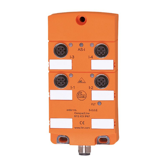
The switch-on and switch-off capacity for triggering solenoids is rated up to 20 W (IEC 60947-5-1, utilisation category DC-13)� Recommendation: For inductive loads use a free wheel diode on the load� ifm electronic offers valve plugs with integrated free wheel diodes� 6 Addressing AC2464 / AC2465 ►... - Page 7 M12 AC2464 / AC2468 1: AS-i + 3: AS-i - connector M12 AC2465 / AC2467 1: AS-i + 2: AUX - 3: AS-i - 4: AUX + AC2464 4 inputs AS-i profile S-0�0�E / extended addressing mode: no Data bit...
- Page 8 AC2467 4 inputs / 4 outputs AS-i profile S-7�A�7 / extended addressing mode: yes Data bit Input Socket I-1/2 I-1/2 I-3/4 I-3/4 Output Socket Inputs Y-circuit Outputs I-1/2 I-3/4 Inputs Outputs 1: sensor supply + 3: external voltage AUX - 2: data input 4: switching output 3: sensor supply +...
- Page 9 AC2468 4 inputs / AS-i profile S-0�A�E / extended addressing mode: yes Data bit Input Socket I-1/2 I-1/2 I-3/4 I-3/4 Inputs Y-circuit I-1/2 I-3/4 Inputs 1: sensor supply + 2: data input 3: sensor supply + 4: data input 5: functional earth (FE)
-
Page 10: Operating And Display Elements
8 Operating and display elements 1: LED AS-i 2: LED FAULT 3: LED IN / OUT 1: LED AS-i 2: LED AUX 3: LED IN / OUT 4: LED FAULT LED AS-i green lights: AS-i voltage supply ok LED AUX green lights: AUX voltage supply ok (AC2465 / AC2467) LED IN / OUT lights: input / output switched... -
Page 11: Maintenance, Repair And Disposal
The operation of the unit is maintenance-free� After use dispose of the unit in an environmentally friendly way in accordance with the applicable national regulations� 10 Technical data Technical data and further information at www�ifm�com� 11 Scale drawing AC2464 / AC2468 M12x1 28,5 M12x1... - Page 12 AC2465 / AC2467 M12x1 28,5 M12x1...
Need help?
Do you have a question about the AC2464 and is the answer not in the manual?
Questions and answers