Table of Contents
Advertisement
Quick Links
Advertisement
Table of Contents

Related Manuals for IFM Electronic A5 interface AC535A


Summary of Contents for IFM Electronic A5 interface AC535A
- Page 1 Operating instructions ATEX ClassicLine module AC535A...
-
Page 2: Table Of Contents
Contents 1 Safety instructions ������������������������������������������������������������������������ 3 2 Functions and features ����������������������������������������������������������������� 3 3 Operating and display elements ��������������������������������������������������� 4 4 Installation ������������������������������������������������������������������������������������ 5 5 Addressing ���������������������������������������������������������������������������������� 10 5�1 Addressing with the AC1154 addressing unit �������������������������� 10 6 Electrical connection������������������������������������������������������������������� 11 7 Operation ������������������������������������������������������������������������������������... -
Page 3: Safety Instructions
Observe the instructions for the safe use in hazardous areas: → Operating instructions (Ex protection related part) for AS-i modules according to EU directive 94/9/EC annex VIII (ATEX) group II, equipment category 3D� If no operating instructions (Ex protection related part) or EC declaration of conformity is supplied with this product in the language of the EU user country, these can be requested from your dealer (see delivery note) or manufacturer (see cover sheet / back)�... -
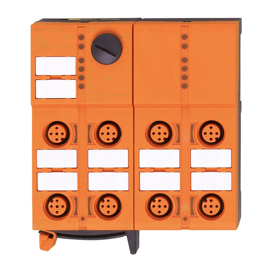
Page 4: Operating And Display Elements
3 Operating and display elements 1: addressing interface 2: LED PWR 3: LED FAULT 4: LED 1 5: labels 6: 8 M12 sockets 7: LED 2 8: LED AUX Scale drawing... -
Page 5: Installation
4 Installation Alignment of the flat cable on delivery Carefully place the yellow and black AS-i flat cable into the profile slot� Mount the upper part� Lock the unit�... - Page 6 With the supplied lower part the flat cable can be aligned in three direc- tions� For the requested direction place the flat cable guide (1) accordingly�...
- Page 7 Settings at the lower part Select the position 1, 2 or 3 depending on the requested flat cable alignment (→). A = factory setting...
- Page 8 Settings at the upper part Then set the selected position at the upper part� To do so, turn the triangle to the corresponding number (fig� D1 and D2)� Use a tool, e�g� a screwdriver (figure D1) or the yellow / black flat cable guide (figure D2)�...
- Page 9 Open the unit Open the unit using a tool as shown (e�g� screwdriver)� Take care in laying the AS-i flat cable, the flat cable should be laid straight for about 15 cm�...
-
Page 10: Addressing
5 Addressing The address is set to 0 at the factory� 5.1 Addressing with the AC1154 addressing unit When mounted and wired the module can be addressed with the addressing cable (E70213) via the integrated addressing interface� If a slave with the extended addressing mode (AC5204) is used in combination with a master of the first generation (version 2�0), the parameter P3 must be 1 and the output bit D3 must be 0*�... -
Page 11: Electrical Connection
6 Electrical connection Connect the plugs of the sensors / actuators to the M12 sockets� Cover the unused sockets with protective caps (E73004)*, the addressing socket with the supplied protective cap� Tightening torque 0�8 Nm� The flat cable end seal (E70413)* must be used if the module is at the end of the cable line�...
Need help?
Do you have a question about the A5 interface AC535A and is the answer not in the manual?
Questions and answers