Table of Contents
Advertisement
Quick Links
Advertisement
Table of Contents

Related Manuals for IFM Electronic AS interface AC506S


Summary of Contents for IFM Electronic AS interface AC506S
- Page 1 Original operating instructions Safe AS-i module AC506S...
-
Page 2: Table Of Contents
Contents 1 Preliminary note ���������������������������������������������������������������������������������������������������3 1�1 Explanation of symbols ����������������������������������������������������������������������������������3 2 Safety instructions �����������������������������������������������������������������������������������������������4 2�1 Safety-related requirements regarding the application ����������������������������������5 3 Items supplied������������������������������������������������������������������������������������������������������5 4 Functions and features ����������������������������������������������������������������������������������������5 5 Function and electrical connection ����������������������������������������������������������������������6 6 Installation������������������������������������������������������������������������������������������������������������7 7 Operating and display elements ������������������������������������������������������������������������13 8 Electrical connection ������������������������������������������������������������������������������������������13 8�1 Mechanical contacts ������������������������������������������������������������������������������������14 8�2 Electronic contacts ��������������������������������������������������������������������������������������14... -
Page 3: Preliminary Note
1 Preliminary note The instructions are part of the unit� They are intended for authorised persons according to the EMC, Low Voltage and Machinery Directives and safety regulations� The instructions contain information about the correct handling of the product� Read the instructions before use to familiarise yourself with operating conditions, installation and operation�... -
Page 4: Safety Instructions
2 Safety instructions • Follow the operating instructions� • In case of non-observance of notes or standards, specially when tampering with and/or modifying the unit, any liability and warranty is excluded� • The unit must be installed, connected and put into operation by a qualified electrician trained in safety technology�... -
Page 5: 2�1 Safety-Related Requirements Regarding The Application
2.1 Safety-related requirements regarding the application It must be ensured that the safety requirements of the respective application correspond to the requirements stated in these instructions� Observe the following requirements: ► Adhere to EN 1088 for interlocking devices associated with guards� ►... -
Page 6: Function And Electrical Connection
5 Function and electrical connection Please also refer to all information in the description of the configuration software (e�g� E7040S) and the operating instructions of the safety monitor� The above documents provide all required instructions concerning installation, configuration, operation and maintenance of the AS-i Safety at Work system� Information on the parameterizable safety functions of the safe AS-i module can be found in the chapter "Monitoring devices"... -
Page 7: Installation
6 Installation ► Carefully place the yellow flat cable (e�g� AC4000) in the lower part� To maintain the indicated protection rating IP 67 ► Close the unused sockets using a bridging plug (E7005S)*, tightening torque 0�6���0�8 Nm� ► Tighten all connected M12 connectors and protective caps, tightening torque 0�6���0�8 Nm�... - Page 8 Alignment of the flat cable on delivery Carefully place the yellow AS-i flat cable into the profile slot� Mount the upper part� Lock the unit�...
- Page 9 With the supplied lower part the flat cable can be aligned in three directions� For the requested direction place the flat cable guide (1) accordingly�...
- Page 10 Settings at the lower part Select the position 1, 2 or 3 depending on the required flat cable alignment (→) A = factory setting...
- Page 11 Settings at the upper part Then set the selected position at the upper part� To do so, turn the triangle to the corresponding number (fig� D1 and D2)� Use a tool, e�g� a screwdriver (fig� D1) or the yellow / black flat cable guide (fig�...
- Page 12 Open the unit Open the unit using a tool as shown (e�g� screwdriver)� Take care in laying the AS-i flat cable, the flat cable should be laid straight for about 15 cm�...
-
Page 13: Operating And Display Elements
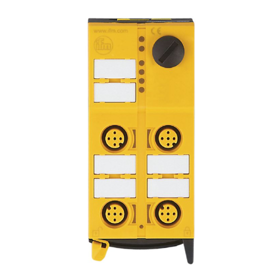
7 Operating and display elements SI-1A SI-2A SI-1B SI-2B 1: Addressing interface 2: 4 M12 sockets 3: LEDs 4: Labels 8 Electrical connection ► Disconnect power� Also disconnect any independently supplied relay load circuits� Do not connect inputs and outputs to an external potential� Use switching contacts with • a current rating ≥ 1 A. -
Page 14: 8�1 Mechanical Contacts
Connection 1: Signal 2: Safety contact (NC) Pin connection CFonnec- Pin 1 Pin 2 Pin 3 Pin 4 S-11A S-12A Output O3 (pnp) S-11B S-12B Output O3 (pnp) S-21A S-22A Output O4 (pnp) S-21B S-22B Output O4 (pnp) 8.1 Mechanical contacts The connected switching contacts must be configured as normally closed in accordance with IEC / EN 60947-5-1 annex K�... -
Page 15: Addressing
A safe separation must be ensured between the external LED and the normally closed contact� In the configuration software the independent two- channel use is only permitted for the monitoring device� Do not connect any of the pins to an external potential since they are electrically connected to the AS-i cable�... -
Page 16: Operation
10 Operation Avoid build-up of dirt and dust on the upper and lower parts so that the locking mechanism is not affected� 1: LED green PWR 2: LED red FAULT 3: Output LEDs O1���O4 LED red O1, O2 alarm LEDs LED yellow O3, O4 signal output 4: LEDs yellow, inputs LED status /... -
Page 17: 10�1 Data Bits
LED status / Operating status designation colour Input safety contact opened yellow safety contact closed LED indications are no safe information� Overload and short circuit of the input supply are signalled to the AS-i master (version 2�1) via the "periphery fault" flag in the status register� 10.1 Data bits Data bit Input... -
Page 18: 10�2 Parameters
Activated input channel Bit sequence D3-D0 XX00 00XX I-1 and I-2 0000 none XXXX Activated alarm output Bit sequence D3-D0 XXX1 XX1X Activated output channel Bit sequence D3-D0 X1XX 1XXX X = random The code words 0000, XX00 and 00XX cause the AS-i safety monitor to bring the installation into the safe state�... -
Page 19: 10�3 Response Times
Assignment of the parameter bits Parameter bit Switching contact socket S-1A S-1B S-2A S-2B Meaning of the logic states P0���P3 1: Contact closed 0: Contact open 10.3 Response times The response time of the safe AS-i module for a safety demand is max� 10 ms� For the calculation of the response time of the complete system the response times of the other components also have to be added (mechanical contacts, safety monitor and external relays or contactors possibly connected to the safety monitor... -
Page 20: Technical Data
12 Technical data AC506S 2 x 2 safe inputs / 2 unsafe LED outputs / 2 unsafe outputs Operating voltage 26�5 ��� 31�6 V DC Current consumption ≤ 280 mA Inputs Wiring DC PNP Voltage supply via AS-i Short-circuit detection Input current typ�... -
Page 21: 12�1 Safety Classification
AS-Interface / version 2�11 and 3�0 / extended addressing mode possible AS-i profile S-7�B�E I/O configuration / ID code 7 [hex] / B�E [hex] AS-i certificate in preparation Maximum number of safety modules per master EN 50295, EN 62061 annex E Housing materials Housing dimensions 103 x 45 x 44�7 mm (H x W x D) -
Page 22: Maintenance, Repair And Disposal
14 Maintenance, repair and disposal If used correctly, no maintenance and repair measures are necessary� Only the manufacturer is allowed to repair the unit� After use dispose of the unit in an environmentally friendly way in accordance with the applicable national regulations� 15 Terms and abbreviations Performance Level Capability of safety-related... -
Page 23: 16�1 Approvals / Certificates
16.1 Approvals / certificates - EC declaration of conformity - TÜV Rheinland - AS-Interface approval number 97201 - UL (cULus)
Need help?
Do you have a question about the AS interface AC506S and is the answer not in the manual?
Questions and answers