Table of Contents
Advertisement
Quick Links
Hitachi Construction Machinery Co., Ltd.
U RL :htt p://w w w . h i ta c hi - c - m . c o m
PRINTED IN THE NETHERLANDS 2013, 09
PART NO.
EM1V1-ENSH2-1(MD1)
Operator's Manual
210LC
250LC
350LC
470LCH
MATERIAL HANDLING MACHINE
(S-SC200H-A)
(S-SC240H-A)
(S-SC330H-B)
(S-SC450H-A)
Serial Machine No.
ZX 210LC-3
202803 and up
ZX 250LC-3
020001 and up
ZX 350LC-3
050002 and up
ZX 470LCH-3 020001 and up
-
3
-
3
-
3
-
3
Serial Front No.
ZX 210LC-3
U1521 and up
ZX 250LC-3
U1521 and up
ZX 350LC-3
U1521 and up
ZX 470LCH-3 U1521 and up
Advertisement
Table of Contents

Related Manuals for Hitachi ZAXIS 210LC-3


Summary of Contents for Hitachi ZAXIS 210LC-3
- Page 1 210LC 250LC 350LC 470LCH MATERIAL HANDLING MACHINE (S-SC200H-A) Hitachi Construction Machinery Co., Ltd. (S-SC240H-A) U RL :htt p://w w w . h i ta c hi - c - m . c o m (S-SC330H-B) (S-SC450H-A) Serial Machine No. Serial Front No.
- Page 2 INTRODUCTION Warranty is provided as a part of Hitachi’s support pro- This Operator’s Manual has been compiled for the Mate- rial Handling Machine of ZX210LC , 250LC , 350LC gram for customers who operate and maintain their 470LCH Hitachi Hydraulic Excavator.
- Page 3 INDEX MACHINE NUMBERS SAFETY SAFETY SIGNS COMPONENTS NAME OPERATOR'S STATION BREAK-IN OPERATING THE ENGINE DRIVING THE MACHINE OPERATING THE MACHINE ASSEMBLING AND DISASSEMBLING TRANSPORTING MAINTENANCE STORAGE SPECIFICATIONS INDEX EM1V1-ENSH2-1(MD1)
- Page 5 MACHINE NUMBERS The manufacturing Nos. explained in this group is the individ- ual number (serial No.) given to each machine and hydraulic components. These numbers are requested when inquiring any information on the machine and/or components. Fill these serial Nos. in the blank spaces in this group to immediately make them available upon request.
- Page 6 MACHINE NUMBERS MEMO ..............................................................................................................................................................................................................................................................................................................................................................................................................................................................................................................................................................................................................................................................................................................................................................................................................................................................................................................................................................................................................................................................................................................................................................................................................................................................................................................................................................................................................................................................................................................................................................................................................................................................................................................................................................................................................................................................................
-
Page 7: Table Of Contents
OPERATING THE MACHINE ........... 5-1 Transport Safely ................S-22 Control Levers (Iso Pattern) ............5-1 Practice Safe Maintenance ............S-23 Control Levers (Hitachi Pattern) ..........5-2 Warn Others of Service Work ........... S-24 Attchment Pedal ................5-3 Support Machine Properly ............S-24 Operation (As for the Machine Stay Clear of Moving Parts ............ - Page 8 CONTENTS Operate the Machine Safely ............5-5 Avoid Pushing Grapple Into Scrap ........... 5-5 Avoid Collapsing Operations by Swing Function ....5-5 Avoid Grading Operation ............5-6 Operate the Machine Slowly and Carefully......5-6 Avoid Crushing Opereations by Pushing and Pulling the Grapple ......... 5-6 Overnight Storage Instructions ..........
-
Page 9: Safety
SAFETY RECOGNIZE SAFETY INFORMATION • These are the SAFETY ALERT SYMBOLS. • When you see these symbols on your machine or in this manual, be alert to the potential for personal injury. • Follow recommended precautions and safe operating practices. 001-E01A-0001 SA-688 UNDERSTAND SIGNAL WORDS... -
Page 10: Follow Safety Instructions
Hitachi Warranty Policy. • Do not use attachments and/or optional parts or equip- ment not authorized by Hitachi. Failure to do so may deteriorate the safety, function, and/or service life of the machine. In addition, personal accident, machine trouble,... -
Page 11: Wear Protective Clothing
SAFETY WEAR PROTECTIVE CLOTHING • Wear close fitting clothing and safety equipment appropri- ate to the job. You may need: A hard hat Safety shoes Safety glasses, goggles, or face shield Heavy gloves Hearing protection Reflective clothing SA-438 Wet weather gear Respirator or filter mask. -
Page 12: General Precautions For Cab
SAFETY GENERAL PRECAUTIONS FOR CAB • Before entering the cab, thoroughly remove all dirt and/ or oil from the soles of your work boots. If any controls such as a pedal is operated while with dirt and/or oil on the soles of the operator’s work boots the operator’s foot may slip off the pedal, possibly resulting in a personal ac- cident. -
Page 13: Use Handholds And Steps
SAFETY USE HANDHOLDS AND STEPS • Falling is one of the major causes of personal injury. • When you get on and off the machine, always face the machine and maintain a three-point contact with the steps and handrails. • Do not use any controls as hand-holds. •... -
Page 14: Fasten Your Seat Belt
SAFETY FASTEN YOUR SEAT BELT • If the machine should overturn, the operator may become injured and/or thrown from the cab. Additionally the opera- tor may be crushed by the overturning machine, resulting in serious injury or death. • Prior to operating the machine, thoroughly examine web- bing, buckle and attaching hardware. -
Page 15: Operate Only From Operator's Seat
SAFETY OPERATE ONLY FROM OPERATOR'S SEAT • Inappropriate engine starting procedures may cause the machine to runaway, possibly resulting in serious injury or death. • Start the engine only when seated in the operator's seat. • NEVER start the engine while standing on the track or on ground. -
Page 16: Precautions For Operations
SAFETY PRECAUTIONS FOR OPERATIONS • Investigate the work site before starting operations. • Be sure to wear close fitting clothing and safety equip- ment appropriate for the job, such as a hard hat, etc. when operating the machine. • Clear all persons and obstacles from area of operation and machine movement. -
Page 17: Investigate Job Site Beforehand
SAFETY INVESTIGATE JOB SITE BEFOREHAND • When working at the soft ground, on the unstable place such as the clippings or on a road shoulder, the machine could tip over, possibly resulting in serious injury or death. • Investigate the configuration and ground conditions of the job site beforehand to prevent the machine from fall- ing and to prevent the ground, stockpiles, or banks from collapsing. -
Page 18: Equipment Of Opg
EQUIPMENT OF OPG • In case the machine is operated in areas where the possibil- ity of falling stones or debris exists, equip genuine Hitachi OPG guard. Contact your nearest Hitachi dealer for installa- tion method of the OPG guard. Depending on the specifica- tions applied to your machine, modification of the machine to meet ROPS standards will be possible. -
Page 19: Precautions For Traveling
SAFETY PRECAUTIONS FOR TRAVELING • Be sure to use a signal person when traveling the machine. • Incorrect travel pedal/lever operation may result in seri- ous injury death or damage to personal property. • Before driving the machine, always confirm that the travel levers/pedals direction corresponds to the travel direc- tion. - Page 20 SAFETY • Driving across the face of a slope or steering on a slope may cause the machine to skid or turnover. If the direc- tion must be changed, move the machine to level ground, then, change the direction to ensure safe operation. •...
-
Page 21: Avoid Injury From Rollaway Accidents
SAFETY AVOID INJURY FROM ROLLAWAY ACCIDENTS • Death or serious injury may result if you attempt to mount or stop a moving machine. To avoid rollaways: • Select level ground when possible to park machine. • Do not park the machine on a grade. •... -
Page 22: Avoid Injury From Back-Over And Swing Accidents
SAFETY AVOID INJURY FROM BACK-OVER AND SWING ACCIDENTS • If any person is present near the machine when backing or swinging the upperstructure, the machine may hit or run over that person, resulting in serious injury or death. To avoid back-over and swing accidents: •... -
Page 23: Ensure Personnel Safety When Leaving The Machine
SAFETY ENSURE PERSONNEL SAFETY WHEN LEAVING THE MACHINE • Be sure to lower the attachment to the ground to securely park the machine. (Refer to the information for parking.) Stop the engine, remove the key, and lock the cab doors. Take all keys with you. -
Page 24: Never Allow Anyone To Enter Under The Attachment
SAFETY NEVER ALLOW ANYONE TO ENTER UNDER THE ATTACHMENT • If the attachment is passed over the working staff or the track cab, falling scraps or contact with the attachment may cause serious personal injury or damage to the machine. Always avoid passing the attachment over personnel. -
Page 25: Avoid Tipping
SAFETY AVOID TIPPING DO NOT ATTEMPT TO JUMP CLEAR OF TIPPING MACHINE --- SERIOUS OR FATAL CRUSHING INJURIES WILL RESULT MACHINE WILL TIP OVER FASTER THAN YOU CAN JUMP FREE FASTEN YOUR SEAT BELT • Depending on the working position or the slope grade, the machine stability may be reduced. -
Page 26: Operate With Caution
SAFETY OPERATE WITH CAUTION • If the front attachment or any other part of the machine hits against an overhead obstacle, such as a bridge, both the machine and the overhead obstacle will be damaged, and personal injury may result as well. •... -
Page 27: If Machine Made Contact With Power Line
SAFETY IF MACHINE MADE CONTACT WITH POWER LINE CAUTION: • Do not panic. Be calm and follow the instructions below. • If the crane is still operable, remove contact from the power line. • Even after arcs disappear, continue to evacuate untill at least the minimum distance spesified from power line is obtained. • If the crane is not operable, if no arcs are observed insaide the cab and if no fire breaks out, remain seated until power is disconnected (until the ma- chine is no longer charged). -
Page 28: Precautions For Lightening
SAFETY PRECAUTIONS FOR LIGHTENING • The machine is vulnerable to lighting strikes. • In the event of an electrical storm, immediately stop opera- tion, and lower the bucket to the ground. Evacuate to a safe place far away from the machine. •... -
Page 29: Park Machine Safely
SAFETY PARK MACHINE SAFELY • Park the machine on solid level ground so that the ma- chine doesn’t run away. • Lower attachment to the ground. • Pull the pilot control shut-odd level to the LOCK position. • Turn auto-idle selector switche OFF to prevent the engine speed from increasing unexpectedly when restarting op- eration. -
Page 30: Transport Safely
SAFETY TRANSPORT SAFELY • Take care the machine may turn over when loading or un- loading the machine onto or off of a truck or trailer. • Observe the related regulations and rules for safe trans- portation. • Select an appropriate truck or trailer for the machine to be transported. -
Page 31: Practice Safe Maintenance
SAFETY PRACTICE SAFE MAINTENANCE To avoid accidents: • Understand service procedures before starting work. • Keep the work area clean and dry. • Do not spray water or steam inside cab. • Never lubricate or service the machine while it is moving. •... -
Page 32: Warn Others Of Service Work
SAFETY • Sufficiently illuminate the work site. Use a maintenance work light when working under or inside the machine. • Always use a work light protected with a guard. In case the light bulb is broken, spilled fuel, oil, antifreeze fluid, or window washer fluid may catch fire. -
Page 33: Prevent Parts From Flying
SAFETY PREVENT PARTS FROM FLYING • Grease in the track adjuster is under high pressure. Failure to follow the precautions below may result in serious injury, blindness, or death. • Do not attempt to remove GREASE FITTING or VALVE AS- SEMBLY. -
Page 34: Prevent Burns
SAFETY PREVENT BURNS Hot spraying fluids: • After operation, engine coolant is hot and under pressure. Hot water or steam is contained in the engine, radiator and heater lines. Skin contact with escaping hot water or steam can cause severe burns. •... -
Page 35: Avoid High-Pressure Fluids
SAFETY AVOID HIGH-PRESSURE FLUIDS • Fluids such as diesel fuel or hydraulic oil under pressure can penetrate the skin or eyes causing serious injury, blindness or death. • Avoid this hazard by relieving pressure before disconnect- ing hydraulic or other lines. •... -
Page 36: Prevent Fires
SAFETY PREVENT FIRES Check for Oil Leaks: • Fuel, hydraulic oil and lubricant leaks can lead to fires. • Check for oil leaks due to missing or loose clamps, kinked hoses, lines or hoses that rub against each other, damage to the oil-cooler, and loose oil-cooler flange bolts. -
Page 37: Evacuating In Case Of Fire
SAFETY EVACUATING IN CASE OF FIRE • If a fire breaks out, evacuate the machine in the following way: • Stop the engine by turning the key switch to the OFF po- sition if there is time. • Use a fire extinguisher if there is time. •... -
Page 38: Avoid Heating Near Pressurized Fluid Lines
SAFETY AVOID HEATING NEAR PRESSURIZED FLUID LINES • Flammable spray can be generated by heating near pres- surized fluid lines, resulting in severe burns to yourself and bystanders. • Do no heat by welding, soldering, or using a torch near pressurized fluid lines or other flammable materials. -
Page 39: Beware Of Asbestos And Silicon Dust And Other Contamination
• Keep bystanders out of the work site during operation. • Asbestos might present in imitation parts. Use only genu- ine Hitachi Parts. PREVENT BATTERY EXPLOSIONS • Battery gas can explode. • Keep sparks, lighted matches, and flame away from the top of battery. -
Page 40: Protect Against Flying Debris
SAFETY PROTECT AGAINST FLYING DEBRIS • f flying debris hit eyes or any other part of the body, serious injury may result. • Guard against injury from flying pieces of metal or debris; wear goggles or safety glasses. • Keep bystanders away from the working area before strik- ing any object. -
Page 41: Handle Chemical Products Safely
• Improperly disposing of waste can threaten the environ- ment and ecology. Potentially harmful waste used with HITACHI equipment includes such items as oil, fuel, coolant, brake fluid, filters, and batteries. • Use leakproof containers when draining fluids. Do not use food or beverage containers that may mislead someone into drinking from them. -
Page 42: Safety Signs
Use the part No. indicated under the right corner of each safety sign illustration when placing an order of it to the Hitachi dealer. SS3113601 SS-2975... -
Page 43: Components Name
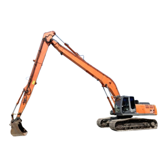
COMPONENTS NAME COMPONENTS NAME 1- Additional Counterweight 2- Boom 3- Arm 4- Boom Cylinder 5- Arm Cylinder 6- Attachment(Grapple) M1V1-SH1-001... - Page 44 COMPONENTS NAME MEMO ..............................................................................................................................................................................................................................................................................................................................................................................................................................................................................................................................................................................................................................................................................................................................................................................................................................................................................................................................................................................................................................................................................................................................................................................................................................................................................................................................................................................................................................................................................................................................................................................................................................................................................................................................................................................................................................................................................
-
Page 45: Operator's Station
OPERATOR'S STATION CAB FEATURES Std. Model 1- Left Control Lever/Horn Switch 2- Left Travel Pedal 3- Left Travel Lever 4- Right Travel Lever 5- Right Travel Pedal 6- Attavhment Pedal 7- Right Control Lever/Power Boost Switch 8- Multi Function Monitor Panel 9- Switch Panel 10- Key Switch 11- Air Conditioner Panel... -
Page 46: Multi Function Monitor Panel
OPERATOR'S STATION MULTI FUNCTION MONITOR PANEL 1 - Work Mode Display 2 - Auto-Idle Display 4 - Auxiliary 5 - Auxiliary 6 - Preheat Display 7 - Work Mode Display 8 - Hour Meter 10 - Fuel Gauge 11 - Mail Display (Optional) 12 - Auxiliary 13 - Fuel Rate Display 14 - Clock... -
Page 47: Work Mode Selection
OPERATOR'S STATION WORK MODE SELECTION IMPORTANT: Select the work mode from the work mode screen. In order to display the work mode screen, push work mode selection key F1 after basic screen displays, or select from main menu. Selecting an Attachment by Using Work Mode Selection Key F1 1. -
Page 48: Selecting A Work Mode From Main Menu
OPERATOR'S STATION Selecting a Work Mode from Main Menu 1. When the basic screen displays, push the menu key and display main menu. 2. Select work mode from main menu by using keys 1 and 2 . Push determination key. Then, the work mode screen displays. -
Page 49: Break-In
BREAK-IN BREAK-IN OPERATION OF NEW MACHINE IMPORTANT: If full loads are imposed to the machine with- out performing break-in operation, score or seizure of the parts may result, possibly shortening the service life of the machine. Sufficiently perform break-in operation. Service life and operational performance of the machine will be greatly affected depending on how the machine is oper- ated during initial stage of operation. - Page 50 BREAK-IN MEMO ..............................................................................................................................................................................................................................................................................................................................................................................................................................................................................................................................................................................................................................................................................................................................................................................................................................................................................................................................................................................................................................................................................................................................................................................................................................................................................................................................................................................................................................................................................................................................................................................................................................................................................................................................................................................................................................................................................
-
Page 51: Operating The Engine
OPERATING THE ENGINE INSPECT MACHINE DAILY BEFORE STARTING WORK Be sure to carry out daily inspections before stating the engine. Refer to the Hydraulic Excavator Operator’s Manual for the en- gine starting/stopping procedures. Check Point Engine 1. Level and if engine oil and coolant are contaminated 2. - Page 52 OPERATING THE ENGINE CAUTION: • Be sure to fasten the seatbelt prior to operating the machine to reduce the possibility of personal injury to the minimum in case tipping over of the machine occurs. • Before operating the machine, be sure to check that the stroke direction of the control levers and pedals matches the movement direction of the ma- chine.
-
Page 53: Driving The Machine
DRIVING THE MACHINE CONTROL LEVERS AND PEDALS WARNING: Before operating the machine, be sure to Front check that the stroke direction of the control levers and pedals matches the movement direction of the Front Idler machine. Align the front attachment in parallel with the longitudinal center direction of the crawlers and position the machine with Left Right... -
Page 54: Traveling On Slopes
DRIVING THE MACHINE TRAVELING ON SLOPES WARNING: • Never attempt to travel on slopes with grade of 10 ° (17%) or more. • Don’t operate actuators other than travel motors while driving up or down slopes. • Avoid driving across the face of a slope, possibly creating hazardous conditions. -
Page 55: Parking The Machine On Slopes
DRIVING THE MACHINE PARKING THE MACHINE ON SLOPES WARNING: Avoid parking machine on slopes. The machine may tip over, possibly resulting in personal injury. PARKING THE MACHINE IMPORTANT: Protect cab electrical components from bad weather. Always close windows, roof vent and cab door when parking the machine. - Page 56 DRIVING THE MACHINE MEMO ..............................................................................................................................................................................................................................................................................................................................................................................................................................................................................................................................................................................................................................................................................................................................................................................................................................................................................................................................................................................................................................................................................................................................................................................................................................................................................................................................................................................................................................................................................................................................................................................................................................................................................................................................................................................................................................................................................
-
Page 57: Operating The Machine
OPERATING THE MACHINE OPERATING THE MACHINE CONTROL LEVERS (ISO PATTERN) WARNING: • If the boom is operated with any part of the opera- tor’s body extended beyond the window frame, crushing accident with the boom may result. • Never extend any part of your body beyond the window frame. Never remove the window bars. • Be completely familiar with the location and func- tion of each control before operation. The machine is equipped with a label showing the control pat- terns of the levers and pedals. -
Page 58: Control Levers (Hitachi Pattern)
OPERATING THE MACHINE CONTROL LEVERS (HITACHI PATTERN) WARNING: • If the boom is operated with any part of the opera- tor’s body extended beyond the window frame, crushing accident with the boom may result. • Never extend any part of your body beyond the window frame. Never remove the window bars. • Be completely familiar with the location and func- tion of each control before operation. -
Page 59: Attchment Pedal
OPERATING THE MACHINE ATTCHMENT PEDAL CAUTION: Turn pedal lock (2) in the LOCK position when attachment pedal (1) is not in use. Do not put foot on the pedal when attachment pedal (1) is not in use. Turn attachment pedal (1) in neutral. Lay pedal lock (2) down forward and lock attachment pedal (1). -
Page 60: Operation (As For The Machine Attached With The Grapple)
OPERATING THE MACHINE OPERATION (AS FOR THE MACHINE ATTACHED WITH THE GRAPPLE) CAUTION: • Before operating the machine, be sure to check that the direction of movement of the control levers and pedals matches the direction of move- ment of the machine. • If the grapple sways, the machine stability is re- duced. Operate the grapple slowly so as to prevent the grapple from swaying as less as possible. -
Page 61: Operate The Machine Safely
OPERATING THE MACHINE OPERATE THE MACHINE SAFELY Pilot control shut-off lever (1) functions to prevent misopera- tion of the machine from occurring if the control levers are accidentally moved when leaving the operator's seat or when entering the cab. CAUTION: Prevent the machine from tipping over and from being involved in a ground collapse. -
Page 62: Avoid Grading Operation
OPERATING THE MACHINE AVOID GRADING OPERATION Do not use this machine to grade scrap heaps. Tipping over of the machine and/or damage to the front attachment may re- sult. SA-1790 OPERATE THE MACHINE SLOWLY AND CAREFULLY • Abrupt operation may cause the machine to tip over due to impact loads. -
Page 63: Overnight Storage Instructions
OPERATING THE MACHINE OVERNIGHT STORAGE INSTRUCTIONS • After day’s operation, drive the machine to solid level ground where there is no possibility of scrap falling, or floods. (Refer to the descriptions for the Parking in the DRIVING THE MACHINE section.) •... -
Page 64: Object Handling
Be sure to consult your autho- rized Hitachi dealer. Check that the specifications of the front and machine to be used meet the specifications shown on the rated lifting load table. - Page 65 OPERATING THE MACHINE 1. Secure sling/chain tightly to the load being lifted. Wear gloves when securing sling/chain. 2. Fasten sling/chain to bucket loop, with the bucket curled and arm retracted. 3. Coordinate hand signals with your signal man before starting. 4.
- Page 66 OPERATING THE MACHINE MEMO ..............................................................................................................................................................................................................................................................................................................................................................................................................................................................................................................................................................................................................................................................................................................................................................................................................................................................................................................................................................................................................................................................................................................................................................................................................................................................................................................................................................................................................................................................................................................................................................................................................................................................................................................................................................................................................................................................................
-
Page 67: Assembling And Disassembling
ASSEMBLING AND DISASSEMBLING INSTALL ATTACHMENT CAUTION: Use a attachment corresponding to the base machine specifications. If a heavier grapple is installed, tipping over of the machine and/or damage to the machine may result. 1. Park the machine on solid level ground. 2. Place the grapple in the position as illustrated to the right. - Page 68 ASSEMBLING AND DISASSEMBLING ZX210LC-3 High-Mount Cab (Single Link Type) Disassembly Conditions A mm B mm Width mm Weight kg Base Machine Single Link Type 4800 2970 3060 15000 Boom 6700 1060 2180 5140 1000 Counterweight 1120 2700 6250 M1V1-SH1-014 Counterweight M1V1-SH1-019 Base Machine (Single Link Type) Boom...
- Page 69 ASSEMBLING AND DISASSEMBLING DISASSEMBLE ZX250LC-3 Std.Cab, High-Mount Cab Disassembly Conditions A mm B mm Width mm Weight kg Std.Cab 5050 3020 3190 14300 Base Machine High-Mount Cab 5050 3140 3190 14400 1.0 m Side Ladder 2380 1390 1210 Handrails 1.5 m Sidewalk Stair 3040 2230...
- Page 70 ASSEMBLING AND DISASSEMBLING ZX250LC-3 High-Mount Cab (Single Link Type) Disassembly Conditions A mm B mm Width mm Weight kg Base Machine Single Link Type 5130 3040 3080 16300 Boom 7220 1020 2450 6190 1180 1320 Counterweight 1120 2840 7900 M1V1-SH1-014 Counterweight M1V1-SH1-019 Base Machine (Single Link Type)
- Page 71 ASSEMBLING AND DISASSEMBLING ZX350LC-3 Std.Cab, High-Mount Cab 1.5 m Disassembly Conditions A mm B mm Width mm Weight kg Std.Cab 5650 3120 3190 19200 Base Machine High-Mount Cab 5650 3290 3190 19300 1.0 m Side Ladder 2380 1390 1210 Handrails 1.5 m Sidewalk Stair 3040...
- Page 72 ASSEMBLING AND DISASSEMBLING ZX350LC- 3 Std.Cab, High-Mount Cab Disassembly Conditions A mm B mm Width mm Weight kg Base Machine Single Link Type 5520 3170 3190 21200 Boom 8740 1040 1170 3500 6400 1430 1100 1510 Counterweight 1250 2950 11300 M1V1-SH1-020 Boom M1V1-SH1-019...
- Page 73 ASSEMBLING AND DISASSEMBLING ZX470LCH-3 Std.Cab, High-Mount Cab Disassembly Conditions A mm B mm Width mm Weight kg with Side Frame 5630 3420 3070 29600 Std.Cab without Side Frame 4640 2660 3070 16300 Base Machine with Side Frame 5630 3420 3070 29700 High-Mount without Side Frame...
- Page 74 ASSEMBLING AND DISASSEMBLING ZX470LCH- 3 Std.Cab, High-Mount Cab Disassembly Conditions A mm B mm Width mm Weight kg with Side Frame 5630 3420 3070 32500 Base Single Link Machine without Side Frame 4640 2660 3070 19200 Boom 9790 1120 1270 4510 7520 1090...
-
Page 75: Transporting By Road
TRANSPOTATION TRANSPORTING BY ROAD Before transporting the machine on public roads, be sure to first research understand and follow all local regulations. • When transporting the machine using a trailer check the width, height, length, and weight of the trailer with the machine loaded. - Page 76 TRANSPOTATION MEMO ..............................................................................................................................................................................................................................................................................................................................................................................................................................................................................................................................................................................................................................................................................................................................................................................................................................................................................................................................................................................................................................................................................................................................................................................................................................................................................................................................................................................................................................................................................................................................................................................................................................................................................................................................................................................................................................................................................
-
Page 77: Maintenance
IMPORTANT: • U s e o n l y r e c o m m e n d e d f u e l a n d lubricants. • Be sure to use only genuine Hitachi parts. Failure to do so may result in serious injury or death and/or machine breakdown. -
Page 78: Check The Hour Meter Regularly
MAINTENANCE CHECK THE HOUR METER REGULARLY • Intervals on the periodic maintenance chart are for operating in normal conditions. If you operate your machine in more adverse conditions, you should service it at SHORTER INTERVALS. • Lubricate, make service checks and adjustments at intervals shown on periodic maintenance guide table. -
Page 79: Prepare Machine For Maintenance
MAINTENANCE PREPARE MACHINE FOR MAINTENANCE Except in special cases, park the machine for maintenance in the following procedures: 1. Park the machine on solid level surface. 2. Lower the grapple with the teeth opened to the ground. 3. Turn the auto-idle selector switch off. 4. -
Page 80: Precautions For Maintenance
MAINTENANCE PRECAUTIONS FOR MAINTENANCE CAUTION: • Never allow anyone to enter below the machine during maintenance. • When aligning pin holes, never insert fingers into the pin holes. • When using a hammer, wear protective equipment such as safety glasses and a hard hat. If flying debris come in contact with eyes or any other part of the body, serious injury may result. • Never enter under the machine when installing a pin. • Service the hydraulic system only after the residual pressure in the system has been released and the tem- perature of each component has cooled. 1. Operate each control lever several times to release the residual pressure from the boom, arm, grapple open/close, swing, and pilot control (incl. -
Page 81: Periodic Replacement Of Parts
MAINTENANCE PERIODIC REPLACEMENT OF PARTS To ensure safe operation, be sure to conduct periodic inspection of the machine. In addition, the parts listed below, if defective, may pose serious safety/fire hazards. It is very difficult to gauge the extent of deterioration, fatigue, or weakening of the parts listed below simply by visual inspection alone. -
Page 82: Grease And Hydraulic Oil
–10 to 40°C Temp. (–4 to 104°F) (14 to 104°F) (–4 to 104°F) (14 to 104°F) (–4 to 104°F) (14 to 104°F) Manufacturer Hitachi Super EX 46HN Idemitsu Kosan Super Hydro 46 WRHU British Petroleum Bartran HV46 Rando Oil Caltex Oil HD46 Rando Oil Texaco INC. -
Page 83: 250Lc- , 350Lc
MAINTENANCE LUBRICATION (ZX210LC- , 250LC- , 350LC- CAUTION: Position the machine as illustrated below for lubrication. Stop the engine. Move the pilot con- trol shut-off lever to the LOCK position. Attach a ”Do not Operate” tag to an easy-to-see place such as the cab door or a control lever to prevent the machine from being unintentionally operated while repairs are being performed. -
Page 84: Precautions For Greasing
MAINTENANCE LUBRICATION (ZX470LCH- CAUTION: Position the machine as illustrated below for lubrication. Stop the engine. Move the pilot con- trol shut-off lever to the LOCK position. Attach a ”Do not Operate” tag to an easy-to-see place such as the cab door or a control lever to prevent the machine from being unintentionally operated while repairs are being performed. -
Page 85: Check Hydraulic Oil Level
MAINTENANCE CHECK HYDRAULIC OIL LEVEL IMPORTANT: If the machine is operated without sufficient supplying of hydraulic oil, air can become mixed into the pump, possibly causing dam- age to the pump. Be sure to check the oil level by following the procedures be- low: •... - Page 86 MAINTENANCE MEMO ..............................................................................................................................................................................................................................................................................................................................................................................................................................................................................................................................................................................................................................................................................................................................................................................................................................................................................................................................................................................................................................................................................................................................................................................................................................................................................................................................................................................................................................................................................................................................................................................................................................................................................................................................................................................................................................................................................8-10...
-
Page 87: Storage
STORAGE PRECAUTIONS FOR LONG TERM MACHINE STORAGE In case the machine is to be stored for longer than one month, pay attention to the following points to prepare next op- eration. Precautions for Long Term Machine Storage Precautionary Point Action to be Taken Machine Cleaning After sufficiently cleaning the machine, remove any soil or other debris ad- hered to the machine. - Page 88 STORAGE MEMO ..............................................................................................................................................................................................................................................................................................................................................................................................................................................................................................................................................................................................................................................................................................................................................................................................................................................................................................................................................................................................................................................................................................................................................................................................................................................................................................................................................................................................................................................................................................................................................................................................................................................................................................................................................................................................................................................................................
-
Page 89: Specifications
SPECIFICATIONS SPECIFICATIONS (ZX210LC-3) Std. Cab Refer to the ZX210LC-3 Hydraulic Excavator Operator’s Manual for specifications other than those described herein. Unit : mm M1V1-SH1-041 Model ZX210LC-3 Type of Front-End Attachment S-SC200H-A Engine ISUZU AI-4HK1XYSA-02 122 kW/2000 min (166 PS/2000 rpm) –1 Std. -
Page 90: Specifications (Zx250Lc- 3 )
SPECIFICATIONS SPECIFICATIONS (ZX210LC-3) High-Mount Cab 1.0 m Refer to the ZX210LC-3 Hydraulic Excavator Operator’s Manual for specifications other than those described herein. Model ZX210LC-3 Type of Front-End Attachment S-SC200H-A –1 Engine ISUZU AI-4HK1XYSA-02 122 kW/2000 min (166 PS/2000 rpm) High-Mount Cab Handrail Height 1000 Ladder or Stairs... -
Page 91: Specifications (Zx350Lc- 3 )
SPECIFICATIONS ZX210LC-3 High-Mount Cab 1.0 m (Side Ladder Type) Unit : mm 1880 M1V1-SH1-042 10-3... -
Page 92: Specifications (Zx470Lch- 3 )
SPECIFICATIONS SPECIFICATIONS (ZX210LC-3) High-Mount Cab 1.5 m Refer to the ZX210LC-3 Hydraulic Excavator Operator’s Manual for specifications other than those described herein. Model ZX210LC-3 Type of Front-End Attachment S-SC200H-A –1 Engine ISUZU AI-4HK1XYSA-02 122 kW/2000 min (166 PS/2000 rpm) High-Mount Cab Handrail Height 1500 Ladder or Stairs... - Page 93 SPECIFICATIONS ZX210LC-3 Unit : mm High-Mount Cab 1.5 m (Sidewalk Stairs Type) 1900 M1V1-SH1-046 10-5...
- Page 94 SPECIFICATIONS SPECIFICATIONS (ZX210LC-3) High-Mount Cab 2 m Refer to the ZX210LC-3 Hydraulic Excavator Operator’s Manual for specifications other than those described herein. Model ZX210LC-3 Type of Front-End Attachment S-SC200H-A –1 Engine ISUZU AI-4HK1XYSA-02 122 kW/2000 min (166 PS/2000 rpm) High-Mount Cab Handrail Height 2000 Ladder or Stairs...
- Page 95 SPECIFICATIONS ZX210LC-3 Unit : mm High-Mount Cab 2.0 m (Sidewalk Stairs Type) 1900 M1V1-SH1-046 10-7...
- Page 96 SPECIFICATIONS SPECIFICATIONS (ZX210LC-3) Lift Cab Refer to the ZX210LC-3 Hydraulic Excavator Operator’s Manual for specifications other than those described herein. Model ZX210LC-3 Type of Front-End Attachment S-SC200H-A –1 Engine ISUZU AI-4HK1XYSA-02 122 kW/2000 min (166 PS/2000 rpm) Single Link Type Cab Lifting Height 2500 Operating Weight...
- Page 97 SPECIFICATIONS ZX210LC-3 Unit : mm Lift Cab (Single Link Type) M1V1-SH1-045 10-9...
- Page 98 SPECIFICATIONS SPECIFICATIONS (ZX250LC-3) Std. Cab • High-Mount Cab 1.0 m Refer to the ZX250LC-3 Hydraulic Excavator Operator’s Manual for specifications other than those described herein. Model ZX250LC-3 Type of Front-End Attachment S-SC240H-A –1 Engine ISUZU AH-4HK1XYSA-01 132 kW/2000 min (180 PS/2000 rpm) Std. Cab High-Mount Cab Handrail Height −...
- Page 99 SPECIFICATIONS ZX250LC-3 Unit : mm Std. Cab M1V1-SH1-041 High-Mount Cab 1.0 m (Side Ladder Type) 1880 M1V1-SH1-042 10-11...
- Page 100 SPECIFICATIONS SPECIFICATIONS (ZX250LC-3) High-Mount Cab 1.5 m Refer to the ZX250LC-3 Hydraulic Excavator Operator’s Manual for specifications other than those described herein. Model ZX250LC-3 Type of Front-End Attachment S-SC240H-A –1 Engine ISUZU AH-4HK1XYSA-01 132 kW/2000 min (180 PS/2000 rpm) High-Mount Cab Handrail Height 1500 Ladder or Stairs...
- Page 101 SPECIFICATIONS ZX250LC-3 Unit : mm High-Mount Cab 1.5 m (Sidewalk Stairs Type) 1900 M1V1-SH1-046 10-13...
- Page 102 SPECIFICATIONS SPECIFICATIONS (ZX250LC-3) High-Mount Cab 2 m Refer to the ZX250LC-3 Hydraulic Excavator Operator’s Manual for specifications other than those described herein. Model ZX250LC-3 Type of Front-End Attachment S-SC240H-A –1 Engine ISUZU AH-4HK1XYSA-01 132 kW/2000 min (180 PS/2000 rpm) High-Mount Cab Handrail Height 2000 Ladder or Stairs...
- Page 103 SPECIFICATIONS ZX250LC-3 Unit : mm High-Mount Cab 2.0 m (Sidewalk Stairs Type) 1900 M1V1-SH1-046 10-15...
- Page 104 SPECIFICATIONS SPECIFICATIONS (ZX250LC-3) Lift Cab Refer to the ZX250LC-3 Hydraulic Excavator Operator’s Manual for specifications other than those described herein. Model ZX250LC-3 Type of Front-End Attachment S-SC240H-A –1 Engine ISUZU AH-4HK1XYSA-01 132 kW/2000 min (180 PS/2000 rpm) Single Link Type Cab Lifting Height 2500 Operating Weight...
- Page 105 SPECIFICATIONS ZX250LC-3 Unit : mm Lift Cab (Single Link Type) M1V1-SH1-045 10-17...
- Page 106 SPECIFICATIONS SPECIFICATIONS (ZX350LC-3) Std. Cab • High-Mount Cab 1.0 m Refer to the ZX350LC-3 Hydraulic Excavator Operator’s Manual for specifications other than those described herein. Model ZX350LC-3 Type of Front-End Attachment S-SC330H-B –1 Engine ISUZU AH-6HK1XYSA-01 202 kW/1900 min (275 PS/1900 rpm) Std. Cab High-Mount Cab Handrail Height −...
- Page 107 SPECIFICATIONS ZX350LC-3 Unit : mm Std. Cab M1V1-SH1-041 High-Mount Cab 1.0 m (Ladder Type) 1970 M1V1-SH1-042 10-19...
- Page 108 SPECIFICATIONS SPECIFICATIONS (ZX350LC-3) High-Mount Cab 1.5 m Refer to the ZX350LC-3 Hydraulic Excavator Operator’s Manual for specifications other than those described herein. Model ZX350LC-3 Type of Front-End Attachment S-SC330H-B –1 Engine ISUZU AH-6HK1XYSA-01 202 kW/1900 min (275 PS/1900 rpm) High-Mount Cab Handrail Height 1500 Ladder or Stairs...
- Page 109 SPECIFICATIONS ZX350LC-3 Unit : mm High-Mount Cab 1.5 m (Sidewalk Stairs Type) 1990 M1V1-SH1-046 10-21...
- Page 110 SPECIFICATIONS SPECIFICATIONS (ZX350LC-3) High-Mount Cab 2 m Refer to the ZX350LC-3 Hydraulic Excavator Operator’s Manual for specifications other than those described herein. Model ZX350LC-3 Type of Front-End Attachment S-SC330H-B –1 Engine ISUZU AH-6HK1XYSA-01 202 kW/1900 min (275 PS/1900 rpm) High-Mount Cab Handrail Height 2000 Ladder or Stairs...
- Page 111 SPECIFICATIONS ZX350LC-3 Unit : mm High-Mount Cab 2.0 m (Sidewalk Stairs Type) 2010 M1V1-SH1-046 10-23...
- Page 112 SPECIFICATIONS SPECIFICATIONS (ZX350LC-3) Lift Cab Refer to the ZX350LC-3 Hydraulic Excavator Operator’s Manual for specifications other than those described herein. Model ZX350LC-3 Type of Front-End Attachment S-SC330H-B –1 Engine ISUZU AH-6HK1XYSA-01 202 kW/1900 min (275 PS/1900 rpm) Single Link Type Cab Lifting Height 2500 Operating Weight...
- Page 113 SPECIFICATIONS ZX350LC-3 Unit : mm Lift Cab (Single Link Type) M1V1-SH1-045 10-25...
- Page 114 SPECIFICATIONS SPECIFICATIONS (ZX470LCH-3) Std. Cab • High-Mount Cab 1.0 m Refer to the ZX470LCH-3 Hydraulic Excavator Operator’s Manual for specifications other than those described herein. Model ZX470LCH-3 Type of Front-End Attachment S-SC450H-A –1 Engine ISUZU AH-6WG1X 260 kW/1800 min (353 PS/1800 rpm) Std. Cab High-Mount Cab Handrail Height −...
- Page 115 SPECIFICATIONS ZX470LCH-3 Unit : mm Std. Cab M1V1-SH1-041 High-Mount Cab 1.0 m (Ladder Type) 1880 M1V1-SH1-042 10-27...
- Page 116 SPECIFICATIONS SPECIFICATIONS (ZX470LCH-3) High-Mount Cab 1.5 m Refer to the ZX470LCH-3 Hydraulic Excavator Operator’s Manual for specifications other than those described herein. Model ZX470LCH-3 Type of Front-End Attachment S-SC450H-A –1 Engine ISUZU AH-6WG1X 260 kW/1800 min (353 PS/1800 rpm) High-Mount Cab Handrail Height 1500 Ladder or Stairs...
- Page 117 SPECIFICATIONS ZX470LCH-3 Unit : mm High-Mount Cab 1.5 m (Sidewalk Stairs Type) 1900 M1V1-SH1-046 10-29...
- Page 118 SPECIFICATIONS SPECIFICATIONS (ZX470LCH-3) High-Mount Cab 2 m Refer to the ZX470LCH-3 Hydraulic Excavator Operator’s Manual for specifications other than those described herein. Model ZX470LCH-3 Type of Front-End Attachment S-SC450H-A –1 Engine ISUZU AH-6WG1X 260 kW/1800 min (353 PS/1800 rpm) High-Mount Cab Handrail Height 2000 Ladder or Stairs...
- Page 119 SPECIFICATIONS ZX470LCH-3 Unit : mm High-Mount Cab 2.0 m (Sidewalk Stairs Type) 1900 M1V1-SH1-046 10-31...
- Page 120 SPECIFICATIONS SPECIFICATIONS (ZX470LCH-3) Lift Cab Refer to the ZX470LCH-3 Hydraulic Excavator Operator’s Manual for specifications other than those described herein. Model ZX470LCH-3 Type of Front-End Attachment S-SC450H-A –1 Engine ISUZU AH-6WG1X 260 kW/1800 min (353 PS/1800 rpm) Single Link Type Cab Lifting Height 2500 Operating Weight...
- Page 121 SPECIFICATIONS ZX470LCH-3 Unit : mm Lift Cab (Single Link Type) M1V1-SH1-045 10-33...
-
Page 122: Working Range • Dimensions
SPECIFICATIONS WORKING RANGE • DIMENSIONS M1V1-SH1-039 Model ZX210LC-3 ZX250LC-3 ZX350LC-3 ZX470LCH-3 A: Max. Arm Pint Reach 11000 12500 14200 16200 B: Max. Arm Pint Height 12280 13710 15660 17500 C: Min. Swing Radius 3190 3770 3850 5300 D: Max. Arm Point Depth 5680 6700 6150 7210... -
Page 123: Lifting Capacities
SPECIFICATIONS LIFTING CAPACITIES NOTE: 1. Lifting capacity of the ZXseries does not exceed 75% of tipping load with the machine on firm, level ground or 87% of full hydraulic capacity. (ISO 10567) 2.*Indicates load limited by hydraulic capacity. 3. Use only working tools that match the specifica- tions of the front attachment. - Page 124 SPECIFICATIONS LIFTING CAPACITIES NOTE: 1. Lifting capacity of the ZXseries does not exceed 75% of tipping load with the machine on firm, level ground or 87% of full hydraulic capacity. (ISO 10567) 2.*Indicates load limited by hydraulic capacity. 3. Use only working tools that match the specifica- tions of the front attachment.
- Page 125 SPECIFICATIONS LIFTING CAPACITIES NOTE: 1. Lifting capacity of the ZXseries does not exceed 75% of tipping load with the machine on firm, level ground or 87% of full hydraulic capacity. (ISO 10567) 2.*Indicates load limited by hydraulic capacity. 3. Use only working tools that match the specifica- tions of the front attachment.
- Page 126 SPECIFICATIONS LIFTING CAPACITIES NOTE: 1. Lifting capacity of the ZXseries does not exceed 75% of tipping load with the machine on firm, level ground or 87% of full hydraulic capacity. (ISO 10567) 2.*Indicates load limited by hydraulic capacity. 3. Use only working tools that match the specifica- tions of the front attachment.
-
Page 127: Index
Move and Operate Machine Safely ...........S-6 Confirm Direction of Machine to Be Driven ......S-10 Movement in Soft Ground ............S-16 Control Levers (Hitachi Pattern) ..........5-2 Multi Function Monitor Panel ............ 1-4 Control Levers (Iso Pattern) ............5-1 Control Levers and Pedals ............4-1 Correct Maintenance and Inspection Procedures .... - Page 128 INDEX Parking the Machine ..............4-3 Transporting by Trailer ..............7-1 Parking the Machine on Slopes ..........4-3 Traveling on Slopes................ 4-2 Periodic Replacement of Parts ........... 8-5 Practice Safe Maintenance ............S-23 Precautions for Greasing............8-7, 8-8 Understand Signal Words .............S-1 Precautions for Lightening ............
- Page 129 Material Handling Machine ZX210LC-3/ZX250LC-3/350LC-3/ZX450LCH-3 Operator’s Manual (Original Instruction) Manual part number. : EM1V1-ENSH2-1(MD1) Hitachi Construction Machinery (Europe) N.V. Address : Siciliёweg 5, 1045 AT, Amsterdam, The Netherlands : http://www.hitachi-c-m.com...
Need help?
Do you have a question about the ZAXIS 210LC-3 and is the answer not in the manual?
Questions and answers