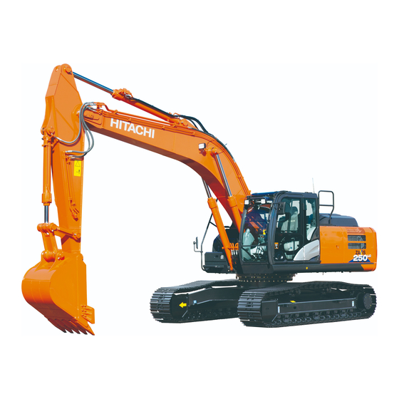
Hitachi ZAXIS 210LC-5N Operator's Manual

Hitachi ZAXIS 210LC-5N Operator's Manual

Super long front
Table of Contents

Advertisement

PART NO.
PART NO.
ENMQHA-1-1
ENMDC1-NASL1-1
Operator's Manual
210LC
Type H15
250LC
Type H18
290LC
Type H18
350LC
Type H18
Type H22
Super Long Front
Serial No.
ZX210LC-5N
330001 and up,
ZX250LC-5N
430001 and up,
ZX290LC-5N
830001 and up,
ZX350LC-5N
930001 and up,
210LC
-5N
Type H15
250LC
-5N
Type H18
300LC
-5N
Type H18
350LC
-5N
Type H18
Type H22
ZX210LC-6N
ZX250LC-6N
ZX300LC-6N
ZX350LC-6N
-6N
-6N
-6N
-6N
340001 and up
440001 and up
840001 and up
940001 and up

Advertisement

Table of Contents
loading

Summary of Contents for Hitachi ZAXIS 210LC-5N

  • Page 1 PART NO. PART NO. ENMQHA-1-1 ENMDC1-NASL1-1 Operator's Manual 210LC 210LC Type H15 Type H15 250LC 250LC Type H18 Type H18 290LC 300LC Type H18 Type H18 350LC 350LC Type H18 Type H18 Type H22 Type H22 Super Long Front Serial No. ZX210LC-5N 330001 and up, ZX210LC-6N...
  • Page 2 (main system). Only the items that differ from those on the Hitachi hydraulic excavator are described in this manual. Refer to the "Operator's Manual for Hitachi Hydraulic Excavator" for other inquiries than described in this manual.
  • Page 3 INDEX MACHINE NUMBER SAFETY SAFETY SIGNS COMPONENTS NAME OPERATOR’S STATION OPERATING THE ENGINE OPERATING THE MACHINE DISASSEMBLING • ASSEMBLING TRANSPORTATION MAINTENANCE SPECIFICATIONS INDEX ENMDC1-NASL1-1...
  • Page 5: Table Of Contents

    CONTENTS MACHINE NUMBER ............1 Maintenance Guide Table ............6-4 Preparations for Inspection and Maintenance .....6-5 SAFETY ................S-1 Maintenance Guide ................6-6 Recognize Safety Information ............S-1 Kind of Oils ..................6-7 Understand Signal Words .............S-1 A. GREASING ..................6-8 Follow Safety Instructions ............S-2 Front Joint Pins ................6-8 Inspect Machine ................S-3 B.
  • Page 6 CONTENTS Shoe Types and Applications ........... 7-33 Bucket Types and Applications ..........7-34 INDEX ................8-1...
  • Page 7: Machine Number

    MACHINE NUMBER The manufacturing Nos. explained in this group is the individual number (serial No.) given to each machine and hydraulic components. These numbers are requested when inquiring any information on the machine and/or components. Fill these serial Nos. in the blank spaces in this group to immediately make them available upon request.
  • Page 8 MACHINE NUMBER MEMO ............................................................................................................................................................................................................................................................................................................................................................................................................................................................................................................................................................................................................................................................................................................................................................................................................................................................................................................................................................................................................................................................................................................................................................................................................................................................................................................................................................................................................................................................................................
  • Page 9: Safety

    SAFETY Recognize Safety Information  These are the SAFETY ALERT SYMBOLS.  When you see these symbols on your machine or in this manual, be alert to the potential for personal injury.  Follow recommended precautions and safe operating practices. SA-688 Understand Signal Words ...
  • Page 10: Follow Safety Instructions

     Do not use attachments and/or optional parts or equipment not authorized by Hitachi. Failure to do so may deteriorate the safety, function, and/or service life of the machine. In addition, personal accident, machine...
  • Page 11: Inspect Machine

    SAFETY Inspect Machine  Inspect your machine carefully each day or shift by walking around it before you start it to avoid personal injury.  In the walk-around inspection be sure to cover all points described in the "Inspect Machine Daily Before Starting" section in the operator’s manual.
  • Page 12: Drive Machine Safely

    SAFETY Drive Machine Safely Expand the arm from vertical position on the face of a slope  Before driving the machine, always confirm that the travel levers/pedals direction corresponds to the direction you wish to drive.  Be sure to detour around any obstructions. ...
  • Page 13 SAFETY  Avoid swinging the upperstructure on slopes. Never attempt to swing the upperstructure downhill. The machine may tip over. If swinging uphill is unavoidable, carefully operate the upperstructure and boom at slow speed.  If the engine stalls on a slope, immediately lower the bucket to the ground.
  • Page 14: Transport Safely

    SAFETY Transport Safely Remove the front attachment and counterweight before transporting the machine.  Take care the machine may turn over when loading or unloading the machine onto or off of a truck or trailer.  Observe the related regulations and rules for safe transportation.
  • Page 15: Avoid Rapid Machine Operation

    SAFETY Avoid Rapid Machine Operation Quick operation may cause the machine to tip over. Especially never attempt to do quick travel or boom lowering operation. SA-2344 Avoid Work Other than Specified This machine increases in weight of the counterweight and has dedicated hydraulic system to operate the super long front attachment.
  • Page 16: Safety Signs

    SAFETY SIGNS SS3088571 SS-2285  Take extra care when removing the stay pin. If the pin of stay is removed, the stay will suddenly drop, your fingers may be pinched by the stay.  Sign indicates a hazard of being hit by the working device of the machine.
  • Page 17: Components Name

    COMPONENTS NAME The super long front or standard front attachment can be installed on this machine. Components Name 1- Boom 2- Arm Cylinder 3- Arm 4- Stay 5- Bucket Cylinder 6- Bucket MDCJ-NASL1-001 7- Counterweight...
  • Page 18: Operator's Station

    OPERATOR'S STATION Layout 1- Left Control Lever/Horn Switch 2- Left Travel Pedal 3- Left Travel Lever 4- Right Travel Lever 5- Right Travel Pedal 6- Right Control Lever/Power Boost Switch 7- Multi Function Monitor Panel 8- Switch Panel 9- Key Switch 10- Regeneration Switch 11- Operator's Seat 12- Cab Door Release Lever...
  • Page 19: Basic Screen (Zx-5N)

    OPERATOR'S STATION Basic Screen (ZX-5N) 1- Work Mode Display 2- Aftertreatment Device Display 3- Power Mode Display 4- Hour Meter, Clock 5- Auxiliary 6- Auxiliary 7- Preheat Display 8- Seat Belt Display 9- Fuel Gauge 10- Sub Meter Display 11- Radio Display 12- Air Conditioner Display 13- Coolant Temperature Gauge 14- Auxiliary...
  • Page 20: Basic Screen (Zx-6N)

    OPERATOR'S STATION Basic Screen (ZX-6N) 1- Work Mode Display 2- Aftertreatment Device Display 3- Power Mode Display 4- Hour Meter, Clock 5- Auxiliary 6- Auxiliary 7- Preheat Display 8- Seat Belt Display 9- Fuel Gauge 10- Sub Meter Display 11- Radio Display 12- Air Conditioner Display 13- Coolant Temperature Gauge 14- Auxiliary...
  • Page 21: Operating The Engine

    OPERATING THE ENGINE Inspect Machine Daily Before Starting Perform the required daily check before starting the engine.  Refer to "Maintenance" section for detailed information. Check Points Check Points 1. Level and contamination of engine oil and coolant 1. Sag, wear and break of crawler 2.
  • Page 22 OPERATING THE ENGINE MEMO ............................................................................................................................................................................................................................................................................................................................................................................................................................................................................................................................................................................................................................................................................................................................................................................................................................................................................................................................................................................................................................................................................................................................................................................................................................................................................................................................................................................................................................................................................................
  • Page 23: Operating The Machine

    OPERATING THE MACHINE Control Lever (ISO Pattern) WARNING:  Never place any part of body beyond window frame. It could be crushed by the boom if boom control lever is accidentally bumped or otherwise engaged. Never remove the window sash bar. ...
  • Page 24: Investigate Job Site Beforehand

    OPERATING THE MACHINE Investigate Job Site Beforehand WARNING:  Assure the safety of work place to prevent the machine from falling, burial or turnover.  Make sure the worksite has sufficient strength to firmly support the machine. When working close to an excavation or at road shoulders, operate the machine with the tracks positioned perpendicular to the cliff face with travel motors at the rear, so that...
  • Page 25: Precautions For Operations

    OPERATING THE MACHINE Precautions for Operations WARNING:  Investigate the work site before starting operations.  Confirm that your machine is equipped with a FOPS cab before working in areas where the possibility of falling stones or debris exist.  When the footing is weak, the machine may turnover.
  • Page 26: Operating Backhoe (Super Long Front Attachment)

    OPERATING THE MACHINE Operating Backhoe (Super Long Front Attachment)  This machine is designed exclusively for light excavation work. Install the standard front attachment for general excavation work.  Use appropriate bucket for the work. (Refer to the "Bucket Types and Applications" in the Specifications section.) ...
  • Page 27: Avoid Operation By Traveling Force

    OPERATING THE MACHINE Avoid operation by traveling force Do not pull or push dirt with the bucket when traveling. Excess force will be applied on each part, and the machine may be damaged. MZX5-03-001 Do not strike the ground with bucket teeth WARNING: Forcibly striking the bucket teeth on the ground may result in personal injury by the flying debris.
  • Page 28: Avoid Hammer Work

    OPERATING THE MACHINE Avoid Hammer Work WARNING: As the bucket body has the curved surface, hammer work or piling work is very dangerous. Doing so may damage the bucket and front attachment. Do not attempt to use the bucket for hammer work and pilling work.
  • Page 29: Avoid Abusive Operation

    OPERATING THE MACHINE Avoid Abusive Operation Do not use travel and do not raise rear of the machine to use the machine's weight as additional digging force. Severe machine damage may result. MZX5-05-005 Avoid Side Load the Bucket Do not side load the bucket. For example, do not swing the bucket to level material or do not strike objects from the side with the bucket.
  • Page 30: Avoid One Side Operation

    OPERATING THE MACHINE Avoid one side operation If load is applied only on one side of wide bucket such as a slope-finishing bucket, the front attachment may be twisted and the parts may be damaged. Avoid using bucket other than specified ...
  • Page 31: Power Mode

    OPERATING THE MACHINE Power Mode Two engine speed modes, ECO and PWR modes are selected by operating the mode switch (1). ECO (Economy) Mode This mode slightly reduces the engine speed according to the operating condition. Digging power is same as the PWR mode.
  • Page 32 OPERATING THE MACHINE MEMO ............................................................................................................................................................................................................................................................................................................................................................................................................................................................................................................................................................................................................................................................................................................................................................................................................................................................................................................................................................................................................................................................................................................................................................................................................................................................................................................................................................................................................................................................................................
  • Page 33: Disassembling • Assembling

    DISASSEMBLING • ASSEMBLING Precautions for Disassembling/Assembling 1. Secure a sufficient solid and level space for disassembling/assembling work. 2. Ensure that the ground is solid. Properly reinforce a soft ground, and ensure the machine is leveled by using a leveler. 3. Disassembly and assembly work is dangerous . Adequate preparation and tools are required for this work.
  • Page 34  After tightening the bolts with specified torque, mark the bolts to prevent miss tightening.  Use Hitachi genuine bolts. If the bolt length is too long or too short, it can not be tightened properly, causing serious accident.
  • Page 35 DISASSEMBLING • ASSEMBLING Precautions for Installation /Removal Front Attachment CAUTION: Remove counterweight if swinging without the boom. Failure to do so may result in machine turnover. 1. Perform disassembly/assembly on a firm, level surface. 2. Align the center of the front attachment with the crawler center.
  • Page 36: Preparation For Work

    Check if the O-ring to be installed in the joint is free from any damage and is seated correctly.  Tighten the hose connector with the specified torque. Refer to the "Operator's Manual for Hitachi Excavator" for tightening torque.  Securely put plugs into the separated hose and pipe ends so that dust does not enter the hydraulic system.
  • Page 37: Precautions For Slinging Work

    DISASSEMBLING • ASSEMBLING Precautions for Slinging Work 1. Determination of signs and commander Determine signs between operator and signal person. Allocate only one signal person for work. Multiple signal persons will confuse workers, causing accident. 2. Installing Protectors Install protectors before placing a wire rope on an object to prevent damage on wire rope and the object to be hoisted.
  • Page 38: Super Long Front Attachment Installation Procedure

    CAUTION:  Bleed air from the hydraulic oil tank. Refer to the Operator’s Manual for Hitachi Excavator.  Bleed air from the hydraulic oil circuit. Refer to the Operator’s Manual for Hitachi Excavator. IMPORTANT:  Prepare a container under the hose connection...
  • Page 39 DISASSEMBLING • ASSEMBLING 3. Install the anti-extraction bolt (2), washer (3), plate (4) and block (5) in this order. ZX210LC-5N, 6N Wrench size : 27 mm Other class Wrench size : 32 mm Tightening Torque : Model Type Tightening Torque ZX210LC-5N, 6N 400 N·m (40 kgf·m) ZX250LC-5N, 6N...
  • Page 40 Installing hoses between the base machine and the boom 1. Release remaining pressure from the piping before installing hoses. Refer to the "Operator's Manual for Hitachi Excavator" for releasing remaining pressure. 2. Install arm cylinder hose (6) and bucket cylinder hose (7). ZX350LC-5N,6N...
  • Page 41 DISASSEMBLING • ASSEMBLING Boom Cylinder Installation WARNING:  NEVER insert your fingers into pin holes when aligning the pin holes. Serious personal injury may result.  Guard against injury from flying pieces of metal. Wear goggles or safety glasses, and safety equipment appropriate to the job.
  • Page 42 DISASSEMBLING • ASSEMBLING 5. Install lubrication piping (16) to the rod side adapter on boom cylinder (10). (2 positions on left and right side) Wrench size : 19 mm Tightening torque : 30 N·m (3.0 kgf·m) 6. Lubricate rod side, bottom side and foot side of boom cylinders (10) (2 used).
  • Page 43 DISASSEMBLING • ASSEMBLING Counterweight Installation ZX210LC-5N,6N ZX250LC-5N,6N ZX290LC-5N ZX300LC-6N ZX350LC-5N,6N Counterweight Weights : Model Type Weight ZX210LC-5N, 6N, ZX250LC-5N, 6N ZX290LC-5N, ZX300LC-6N ZX210LC-5N, 6N 5300 kg W178-02-02-003 ZX250LC-5N, 6N 6800 kg ZX290LC-5N ZX300LC-6N 6500 kg 7400 kg ZX350LC-5N, 6N 8900 kg 1.
  • Page 44 DISASSEMBLING • ASSEMBLING Arm Installation WARNING:  NEVER insert your fingers into pin holes when aligning the pin holes. Serious personal injury may result.  Guard against injury from flying pieces of metal. Wear goggles or safety glasses, and safety equipment appropriate to the job.
  • Page 45 DISASSEMBLING • ASSEMBLING 5. Slowly lower arm (22) end onto the ground. Hoist the arm 6. Align the hole on arm (21) and hole on the arm cylinder cylinder by using by extending/retracting arm cylinder. Install shims and a crane. pin (24), and then install the retaining bolt.
  • Page 46 Installing hoses between the boom and arm 1. Release remaining pressure from the piping before installing hoses. Refer to the "Operator's Manual for Hitachi Excavator" for bleeding air. CAUTION: Do not release pressure from the hydraulic circuit of the boom and arm cylinders. Releasing pressure is dangerous as the boom and arm may fall down under its own weight.
  • Page 47 DISASSEMBLING • ASSEMBLING Connecting Lubrication Hose and Lubricate 1. Install lubrication hoses between the arm. Arm lubrication hose : At the top of the arm cylinder (a) Wrench size : 19 mm Tightening Torque : Model Type Tightening Torque ZX210LC-5N, 6N ZX250LC-5N, 6N M1T1-SL1-007 ZX290LC-5N...
  • Page 48 DISASSEMBLING • ASSEMBLING Bucket Installation O-Ring Shift WARNING:  NEVER insert your fingers into pin holes when aligning the pin holes. Serious personal injury may result.  Guard against injury from flying pieces of metal. Wear goggles or safety glasses, and safety equipment appropriate to the job.
  • Page 49: Super Long Front Attachment Removal Procedure

    DISASSEMBLING • ASSEMBLING Super Long Front Attachment Removal Procedure Bucket Removal O-Ring Shift WARNING:  NEVER insert your fingers into pin holes when aligning the pin holes. Serious personal injury may result. CAUTION: When driving the connecting pins in or out, guard against injury from flying pieces of metal or debris.
  • Page 50 Removing Hoses between the Boom And Arm CAUTION:  Bleed air from the hydraulic oil tank. Refer to the Operator’s Manual for Hitachi Excavator.  Bleed air from the hydraulic oil circuit. Refer to the Operator’s Manual for Hitachi Excavator.
  • Page 51 Take care not to allow wire rope to slide on the cylinder. 4. Release remaining pressure from the piping of arm cylinder (21). M1T1-SL1-001 Refer to the "Operator's Manual for Hitachi Excavator" for releasing pressure. 5. Remove pin (24) connecting arm cylinder (21) and arm (22).
  • Page 52 DISASSEMBLING • ASSEMBLING Arm Removal WARNING:  NEVER insert your fingers into pin holes when aligning the pin holes. Serious personal injury may result.  Guard against injury from flying pieces of metal. Wear goggles or safety glasses, and safety 1.5 m equipment appropriate to the job.
  • Page 53 DISASSEMBLING • ASSEMBLING Counterweight Removal ZX210LC-5N, 6N ZX250LC-5N, 6N ZX290LC-5N ZX300LC-6N Counterweight Weights : Model Type Weight ZX210LC-5N, 6N 5300 kg ZX250LC-5N, 6N 6800 kg ZX290LC-5N ZX300LC-6N 6500 kg WARNING: When the front attachment is removed, also remove the counterweight. Otherwise, the machine has a risk of turnover.
  • Page 54 DISASSEMBLING • ASSEMBLING Counterweight Removal ZX350LC-5N, 6N Wire Rope Counterweight Weights: Model Type Counterweight 7400 kg ZX350LC-5N, 6N 8900 kg 1. Attach wire ropes on the upper bracket of counterweight. Slightly hoist the wire and remove wire slackness. 2. Remove bolts (19) and washer (18). Hoist and remove ZX350LC-5N, 6N counterweight (17).
  • Page 55 1. Ensure that the boom end is placed on a wooden block. 2. Release remaining pressure from the piping of boom cylinder (10). Refer to the "Operator's Manual for Hitachi Excavator" for releasing pressure. W105-04-01-002 3. Remove lubrication piping (16) to the rod side adapter on boom cylinder (10).
  • Page 56 Removal of Hoses between the Machine and Boom 1. Release remaining pressure from the piping before removing hoses. Refer to the "Operator's Manual for Hitachi Excavator" for releasing pressure. 2. Remove arm hose (6) and bucket hose (7) between the base machine and the boom.
  • Page 57 DISASSEMBLING • ASSEMBLING Boom Removal WARNING:  NEVER insert your fingers into pin holes when aligning the pin holes. Serious personal injury may result.  Guard against injury from flying pieces of metal. Wear goggles or safety glasses, and safety equipment appropriate to the job.
  • Page 58 DISASSEMBLING • ASSEMBLING MEMO ............................................................................................................................................................................................................................................................................................................................................................................................................................................................................................................................................................................................................................................................................................................................................................................................................................................................................................................................................................................................................................................................................................................................................................................................................................................................................................................................................................................................................................................................................................
  • Page 59: Transportation

    TRANSPORTATION Transporting by Road When transporting the machine on public roads, be sure to first understand and follow all local regulations. 1. When transporting using a trailer, check the width, height, length and weight of the trailer with the machine loaded.
  • Page 60: Loading/Unloading On A Trailer

    TRANSPORTATION Loading/Unloading on a Trailer Always load and unload the machine on a firm, level surface. WARNING: Be sure to use a loading dock or a ramp for loading/unloading. Ramp/Loading Dock: 1. Before loading, thoroughly clean the ramps, loading dock and flatbed. Dirty ramps, loading docks, and flatbeds with oil, mud, or ice on them are slippery and dangerous.
  • Page 61 TRANSPORTATION Loading/Unloading WARNING:  Always turn the auto-idle switch OFF and turn the power mode switch to (PWR) or (ECO) position when loading or unloading the machine. In the auto-idle mode, speed may automatically increase.  Always select the slow speed mode with the travel mode switch.
  • Page 62 TRANSPORTATION Loading the machine (with front attachment) WARNING: If the front attachment is installed, lower the front attachment as possible before loading/ unloading the machine. Drive the machine in reverse with the front attachment side at the rear when loading the machine. 1.
  • Page 63 TRANSPORTATION Unloading the machine (without front attachment) WARNING: The rear end of the flatbed where it meets the ramp is a sudden bump. Take care when traveling over it. Drive the machine forward when unloading the machine. 15 ° or less 1.
  • Page 64 TRANSPORTATION Unloading the machine (with front attachment) WARNING: The rear end of the flatbed where it meets the ramp is a sudden bump. Take care when traveling over it. Drive the machine forward when unloading the machine. 1. Remove stay (1). IMPORTANT: Make sure that the angle of the boom and the arm is kept between 90 to 110 °...
  • Page 65 TRANSPORTATION Detach/Attach Method of Stay WARNING: The stay (1) may fall when the pin is removed from the stay (1). CAUTION: The bucket may interfere in the stay (1) depending on the type of the bucket. Carefully select the bucket to be installed. 1.
  • Page 66: Dimensions And Weight For Transportation (Zx-5N)

    TRANSPORTATION Dimensions and Weight for Transportation (ZX- 1. Base Machine Shoe Width Weight Model Width (mm) (mm) (mm) (kg) (mm) 2590 12000 ZX210LC-5N 4890 3020 2690 12300 2790 12600 3190 13500 ZX250LC-5N 5020 3080 3290 13800 3390 14100 3190 16600 ZX290LC-5N 5020 3080...
  • Page 67 TRANSPORTATION 5. Counterweight Width Weight Model (mm) (mm) (mm) (kg) ZX210LC-5N 1150 2664 5300 ZX250LC-5N 1170 2840 6800 ZX290LC-5N 1170 2840 6800 7400 ZX350LC-5N 1250 2950 8900 ZX210LC-5N, ZX250LC-5N ZX290LC-5N MDC1-NASL1-002 ZX350LC-5N MDC1-NASL1-003...
  • Page 68: Dimensions And Weight For Transportation (Zx-6N)

    TRANSPORTATION Dimensions and Weight for Transportation (ZX- 1. Base Machine Shoe Width Weight Model Width (mm) (mm) (mm) (kg) (mm) 2990 13600 ZX210LC-6N 4900 3030 3090 14000 3190 14300 3190 14000 ZX250LC-6N 5210 3090 3290 14800 3390 15100 3190 18700 ZX300LC-6N 5540 3200...
  • Page 69 TRANSPORTATION 5. Counterweight Width Weight Model (mm) (mm) (mm) (kg) ZX210LC-6N 1130 2670 5300 ZX250LC-6N 1140 2840 6800 ZX300LC-6N 1140 2840 6500 1250 2950 7400 ZX350LC-6N 1250 2950 8900 ZX210LC-6N, ZX250LC-6N ZX300LC-6N MDC1-NASL1-002 ZX350LC-6N MDC1-NASL1-003 5-11...
  • Page 70: Lifting Machine

    TRANSPORTATION Lifting Machine WARNING:  Make sure that you use lifting wire and other lifting tools that are not damaged or deteriorated and that have sufficient capacity required for the work.  Be sure to contact your authorized dealer for correct lifting procedure, and size and kinds of lifting wire ropes and lifting tools.
  • Page 71: Do Not Hoist Whole Machine

    Never attempt to hoist the whole machine. Always hoist the machine after removing the super long front attachment and the counterweight. Refer to the “Operator’s Manual for Hitachi Excavator” for hoisting the whole machine with the standard front attachment. Support WARNING: Never use the lifting eyes on the additional counterweight for hoisting the main body.
  • Page 72 TRANSPORTATION MEMO ............................................................................................................................................................................................................................................................................................................................................................................................................................................................................................................................................................................................................................................................................................................................................................................................................................................................................................................................................................................................................................................................................................................................................................................................................................................................................................................................................................................................................................................................................................5-14...
  • Page 73: Maintenance

    IMPORTANT:  Use only recommended fuel and lubricants.  Be sure to use only genuine Hitachi parts. Failure to do so may result in serious injury or death and/or machine breakdown.  Failure to use recommended fuel, lubricants, and genuine Hitachi parts will result in loss of Hitachi product warranty.
  • Page 74 It is not necessary to check or operate the communication terminal however if any abnormality is found, consult your nearest Hitachi dealer. Before installing any covering attachment such as a head guard, consult your nearest Hitachi dealer. Never spray water on the communication terminal and the wirings.
  • Page 75: Check The Hour Meter Regularly

    MAINTENANCE Check the Hour Meter Regularly Refer to the List of Check and Maintenance for information about lubricants, check and adjustment intervals. The maintenance guide table is affixed in the back of the tool box cover. Refer to the next page. This manual recommends grouping the intervals into three categories as follows: Daily...
  • Page 76: Maintenance Guide Table

    MAINTENANCE Maintenance Guide Table The maintenance guide table is affixed in the utility space. Lubricate and/or service the parts at the intervals as instructed in the table so that all necessary maintenance can be performed regularly.  Symbol Marks The following marks are used in the maintenance guide table.
  • Page 77: Preparations For Inspection And Maintenance

    MAINTENANCE Preparations for Inspection and Maintenance Except in special cases, park the machine by following the procedure before servicing the machine. 1. Park the machine on a solid and level surface. 2. Lower the bucket to the ground. M104-07-021 3. Turn the auto-idle switch OFF. 4.
  • Page 78: Maintenance Guide

    IMPORTANT: Grease bucket and link pivots every day until break-in operation (50 hours) is complete. When a bucket which does not have clearance adjustment mechanism such as slope-finishing bucket, or a genuine Hitachi hoe bucket before EX-5 model, or an attachment other than genuine Hitachi bucket is used, grease two pins every 250 hours.
  • Page 79 Lithium Grease Application Front Attachment Joint Pins, Swing Bearing, Swing, Internal Gear. Air Temp. -20 to 40 °C (-4 to 104 °F) Manufacturer Hitachi Grease SEP2 Hitachi Hitachi Grease EP-2 Daphne Eponex Grease EP No.2 Idemitsu Kosan Daphne Eponex Grease No.2 JX Nippon Oil &...
  • Page 80 MAINTENANCE A. GREASING Front Joint Pins --- every 500 hours 250 hours for only first time. Lubricate all fittings shown in the figure. M178-07-007  Boom Cylinder Bottom Side M157-07-156  Boom Foot M157-07-155...
  • Page 81 MAINTENANCE  Boom and Arm Joint Pin, Arm Cylinder Rod Pin and Bucket Cylinder Bottom Pin. M157-07-157  Boom Cylinder Rod Pins and Arm Cylinder Bottom Pin. M157-07-155...
  • Page 82: Hydraulic System

    MAINTENANCE B. HYDRAULIC SYSTEM Inspection and Maintenance of Hydraulic Equipment IMPORTANT: Never adjust parts of engine fuel system or hydraulic equipment. CAUTION: When checking and/or servicing the hydraulic components, pay special attention to the following points. 1. Be sure that the machine is parked on a level, firm surface before servicing hydraulic equipment.
  • Page 83 MAINTENANCE IMPORTANT:  When connecting hydraulic hoses and pipes, take special care to keep seal surfaces free from dirt and to avoid damaging them.  Wash hoses, pipes, and the tank interior with a washing liquid and thoroughly wipe it out before reconnecting them.
  • Page 84: Check Hydraulic Oil Level

    MAINTENANCE Check Hydraulic Oil Level ---daily 1. Park the machine on solid and level ground with the bucket cylinder fully extended and the arm cylinder fully retracted. Lower the bucket on the ground as shown to the right. Stop the engine. M104-07-021 2.
  • Page 85: Miscellaneous

    MAINTENANCE C. MISCELLANEOUS Tightening and Retightening Torque of Nuts and Bolts --- every 250 hours (first time after 50 hours) Tighten to torque shown if any are loose. Bolts and nuts should be replaced with those of the same or higher grade. Check tightness after the first 50 hours then every 250 hours.
  • Page 86 MAINTENANCE Tightening Torque Chart Hexagon Wrench Socket Bolt Bolt Dia. Socket Bolt Wrench size Wrench size N·m (kgf·m) N·m (kgf·m) N·m (kgf·m) N·m (kgf·m) 3.3 to 4.2 (0.3 to 0.4) (3.0) (2.0) (1.0) (2.0) (6.5) (5.0) (2.0) (5.0) (11) (9.0) (3.5) (9.0) (18)
  • Page 87: Specifications

    SPECIFICATIONS Specifications ZX210LC-5N MDAA-12-007 Model ZX210LC-5N Type of Front-End Attachment – Bucket Capacity (Heaped) PCSA 0.45, CECE 0.40 Operating Weight kg (lb) 21300 (47000) Base Machine Weight kg (lb) 16970 (37400) Engine – Isuzu AM-4HK1XZSA-03 122 kW/2000 min (166 PS/2000 rpm) Overall Width (Excluding mm (ft·in) 3190 (10’6”)
  • Page 88: Working Ranges Zx210Lc-5N Super Long Front Attachment (Type H15)

    SPECIFICATIONS Working Ranges ZX210LC-5N Super Long Front Attachment (Type H15) MDCJ-NASL1-002 A: Maximum Digging Reach mm (ft·in) 15340 (50’4”) B: Maximum Digging Reach (on ground) mm (ft·in) 15230 (49’12”) C: Minimum Level Crowding Distance mm (ft·in) 1680 (5’6”) D: Maximum Digging Depth mm (ft·in) 11980 (39’4”) E: Maximum Vertical Wall Depth...
  • Page 89: Shoe Types And Applications

    SPECIFICATIONS Shoe Types and Applications ZX210LC-5N Type 600 mm (24”) 700 mm (28”) 800 mm (31”) Shoe Width Grouser Shoe Grouser Shoe Grouser Shoe For Ordinary Ground Application For Weak Footing (Option) (Standard) 20600 21000 21300 Operating Weight (lb) (45400) (46300) (47000) 16270...
  • Page 90: Bucket Types And Applications

    The maximum allowable weight is determined by Hitachi standards. If the total load exceeds this value, it may cause machine turnover or damage on the front attachment. Select a bucket having capacity and weight with maximum allowable loading weight.
  • Page 91 SPECIFICATIONS Specifications ZX250LC-5N MDCA-SL1-048 Model ZX250LC-5N Type of Front-End Attachment – Bucket Capacity (Heaped) PCSA 0.40, CECE 0.33 Operating Weight kg (lb) 25100 (55300) Base Machine Weight kg (lb) 19530 (43100) Engine – Isuzu AL-4HK1XZSA-02 132 kW/2000 min (180 PS/2000 rpm) Overall Width (Excluding mm (ft·in) 3290 (10’10”)
  • Page 92: Working Ranges Zx250Lc-5N Super Long Front Attachment (Type H18)

    SPECIFICATIONS Working Ranges ZX250LC-5N Super Long Front Attachment (Type H18) MDCJ-NASL1-003 A: Maximum Digging Reach mm (ft·in) 18250 (59’11”) B: Maximum Digging Reach (on ground) mm (ft·in) 18160 (59’7”) C: Minimum Level Crowding Distance mm (ft·in) 1640 (5’5”) D: Maximum Digging Depth mm (ft·in) 14360 (47’1”) E: Maximum Vertical Wall Depth...
  • Page 93: Shoe Types And Applications

    SPECIFICATIONS Shoe Types and Applications ZX250LC-5N Type 600 mm (24”) 700 mm (28”) 800 mm (31”) Shoe Width Grouser Shoe Grouser Shoe Grouser Shoe For Ordinary Ground Application For Weak Footing (Option) For Weak Footing (Option) (Standard) 24300 24800 25100 Operating Weigh (lb) (53600)
  • Page 94: Bucket Types And Applications

    The maximum allowable weight is determined by Hitachi standards. If the total load exceeds this value, it may cause machine turnover or damage on the front attachment. Select a bucket having capacity and weight with maximum allowable loading weight.
  • Page 95 SPECIFICATIONS Specifications ZX290LC-5N MDCA-SL1-049 Model ZX290LC-5N Type of Front-End Attachment – Bucket Capacity (Heaped) PCSA 0.45, CECE 0.40 Operating Weight kg (lb) 28700(63300) Base Machine Weight kg (lb) 23000(50700) Engine – Isuzu AL-4HK1XZSA-01 140 kW/2100 min (190 PS/2100 rpm) Overall Width (Excluding mm (ft·in) 3390 (11’2”) back mirrors)
  • Page 96: Working Ranges Zx290Lc-5N Super Long Front Attachment (Type H18)

    SPECIFICATIONS Working Ranges ZX290LC-5N Super Long Front Attachment (Type H18) MDCJ-NASL1-004 A: Maximum Digging Reach mm (ft·in) 18260 (59’11”) B: Maximum Digging Reach (on ground) mm (ft·in) 18150 (59’7”) C: Minimum Level Crowding Distance mm (ft·in) 1600 (5’3”) D: Maximum Digging Depth mm (ft·in) 14440 (47’5”) E: Maximum Vertical Wall Depth...
  • Page 97: Shoe Types And Applications

    SPECIFICATIONS Shoe Types and Applications ZX290LC-5N Type 600 mm (24”) 700 mm (28”) 800 mm (31”) Shoe Width Grouser Shoe Grouser Shoe Grouser Shoe For Ordinary Ground Application For Weak Footing (Option) (Standard) 27700 28300 28700 Operating Weight (lb) (61100) (62400) (63300) 22000...
  • Page 98: Bucket Types And Applications

    The maximum allowable weight is determined by Hitachi standards. If the total load exceeds this value, it may cause machine turnover or damage on the front attachment. Select a bucket having capacity and weight with maximum allowable loading weight.
  • Page 99 SPECIFICATIONS Specifications ZX350LC-5N MDCA-SL1-050 Model ZX350LC-5N Type of Front-End Attachment – Bucket Capacity (Heaped) PCSA 0.52, CECE 0.45 PCSA 0.40, CECE 0.33 Operating Weight kg (lb) 32800 (72300) 34300 (75600) Base Machine Weight kg (lb) 25680 (56600) 27050 (75600) Engine –...
  • Page 100: Working Ranges Zx350Lc-5N Super Long Front Attachment (Type H18)

    SPECIFICATIONS Working Ranges ZX350LC-5N Super Long Front Attachment (Type H18) MDCJ-NASL1-005 A: Maximum Digging Reach mm (ft·in) 18280 (59’12”) B: Maximum Digging Reach (on ground) mm (ft·in) 18160 (59’7”) C: Minimum Level Crowding Distance mm (ft·in) 1950 (6’5”) D: Maximum Digging Depth mm (ft·in) 14030 (46’0”) E: Maximum Vertical Wall Depth...
  • Page 101: Working Ranges Zx350Lc-5N Super Long Front Attachment (Type H22)

    SPECIFICATIONS Working Ranges ZX350LC-5N Super Long Front Attachment (Type H22) MDCJ-NASL1-006 A: Maximum Digging Reach mm (ft·in) 22020 (72’3”) B: Maximum Digging Reach (on ground) mm (ft·in) 21920 (71’11”) C: Minimum Level Crowding Distance mm (ft·in) 2640 (8’8”) D: Maximum Digging Depth mm (ft·in) 17270 (56’8”) E: Maximum Vertical Wall Depth...
  • Page 102: Shoe Types And Applications

    SPECIFICATIONS Shoe Types and Applications ZX350LC-5N Type 600 mm (24”) 700 mm (28”) 800 mm (31”) Shoe Width Grouser Shoe Grouser Shoe Grouser Shoe For Ordinary Ground Application For Weak Footing (Option) (Standard) 31800 32400 32800 Operating Weight (lb) (70100) (71400) (72300) 33300...
  • Page 103: Bucket Types And Applications

    The maximum allowable weight is determined by Hitachi standards. If the total load exceeds this value, it may cause machine turnover or damage on the front attachment. Select a bucket having capacity and weight with maximum allowable loading weight.
  • Page 104 SPECIFICATIONS Specifications ZX210LC-6N MDC1-NASL1-005 Model ZX210LC-6N Type of Front-End Attachment – Bucket Capacity (Heaped) PCSA 0.45, CECE 0.40 Operating Weight kg (lb) 23100 (50900) Base Machine Weight kg (lb) 18600 (41000) Engine – 122 kW/2000 min –1 (166 PS/2000 rpm) Overall Width (Excluding mm (ft·in) 3090 (10’2”)
  • Page 105: Working Ranges Zx210Lc-6N Super Long Front Attachment (Type H15)

    SPECIFICATIONS Working Ranges ZX210LC-6N Super Long Front Attachment (Type H15) MDC1-NASL1-006 A: Maximum Digging Reach mm (ft·in) 15330 (50’4”) B: Maximum Digging Reach (on ground) mm (ft·in) 15220 (49’11”) C: Minimum Level Crowding Distance mm (ft·in) 1650 (5’5”) D: Maximum Digging Depth mm (ft·in) 11980 (39’4”) E: Maximum Vertical Wall Depth...
  • Page 106: Shoe Types And Applications

    SPECIFICATIONS Shoe Types and Applications ZX210LC-6N Type 600 mm (24”) 700 mm (28”) 800 mm (31”) Shoe Width Grouser Shoe Grouser Shoe Grouser Shoe For Ordinary Ground Application For Weak Footing (Option) (Standard) 22400 22800 23100 Operating Weight (lb) (49400) (50300) (50900) 17900...
  • Page 107: Bucket Types And Applications

    The maximum allowable weight is determined by Hitachi standards. If the total load exceeds this value, it may cause machine turnover or damage on the front attachment. Select a bucket having capacity and weight with maximum allowable loading weight.
  • Page 108 SPECIFICATIONS Specifications ZX250LC-6N MDC1-NASL1-007 Model ZX250LC-6N Type of Front-End Attachment – Bucket Capacity (Heaped) PCSA 0.40, CECE 0.33 Operating Weight kg (lb) 26200 (57800) Base Machine Weight kg (lb) 20400 (45000) Engine – Isuzu AQ-4HK1XASA-01 132 kW/2000 min (180 PS/2000 rpm) –1 Overall Width (Excluding mm (ft·in)
  • Page 109: Working Ranges Zx250Lc-6N Super Long Front Attachment (Type H18)

    SPECIFICATIONS Working Ranges ZX250LC-6N Super Long Front Attachment (Type H18) MDC1-NASL1-008 A: Maximum Digging Reach mm (ft·in) 18250 (59’11”) B: Maximum Digging Reach (on ground) mm (ft·in) 18150 (59’7”) C: Minimum Level Crowding Distance mm (ft·in) 1640 (5’5”) D: Maximum Digging Depth mm (ft·in) 14350 (47’1”) E: Maximum Vertical Wall Depth...
  • Page 110: Shoe Types And Applications

    SPECIFICATIONS Shoe Types and Applications ZX250LC-6N Type 600 mm (24”) 700 mm (28”) 800 mm (31”) Shoe Width Grouser Shoe Grouser Shoe Grouser Shoe For Ordinary Ground Application For Weak Footing (Option) For Weak Footing (Option) (Standard) 25700 26200 26500 Operating Weight (lb) (56700)
  • Page 111: Bucket Types And Applications

    The maximum allowable weight is determined by Hitachi standards. If the total load exceeds this value, it may cause machine turnover or damage on the front attachment. Select a bucket having capacity and weight with maximum allowable loading weight.
  • Page 112 SPECIFICATIONS Specifications ZX300LC-6N MDC1-NASL1-009 Model ZX300LC-6N Type of Front-End Attachment – Bucket Capacity (Heaped) PCSA 0.45, CECE 0.40 Operating Weight kg (lb) 30800 (67900) Base Machine Weight kg (lb) 24900 (54900) Engine – Isuzu AQ-6HK1XASA-02S 186kW/1900 min (253 PS/1900 rpm) Overall Width (Excluding mm (ft·in) 3290 (10’10”)
  • Page 113: Working Ranges Zx300Lc-6N Super Long Front Attachment (Type H18)

    SPECIFICATIONS Working Ranges ZX300LC-6N Super Long Front Attachment (Type H18) MDC1-NASL1-010 A: Maximum Digging Reach mm (ft·in) 18250 (59’11”) B: Maximum Digging Reach (on ground) mm (ft·in) 18140 (59’6”) C: Minimum Level Crowding Distance mm (ft·in) 1600 (5’3”) D: Maximum Digging Depth mm (ft·in) 13760 (45’2”) E: Maximum Vertical Wall Depth...
  • Page 114: Shoe Types And Applications

    SPECIFICATIONS Shoe Types and Applications ZX300LC-6N Type 600 mm (24”) 700 mm (28”) 800 mm (31”) Shoe Width Grouser Shoe Grouser Shoe Grouser Shoe For Ordinary Ground Application For Weak Footing (Option) (Standard) 29800 30400 30800 Operating Weight (lb) (65700) (67000) (67900) 23900...
  • Page 115: Bucket Types And Applications

    The maximum allowable weight is determined by Hitachi standards. If the total load exceeds this value, it may cause machine turnover or damage on the front attachment. Select a bucket having capacity and weight with maximum allowable loading weight.
  • Page 116 SPECIFICATIONS Specifications ZX350LC-6N MDC1-NASL1-011 Model ZX350LC-6N Type of Front-End Attachment – Bucket Capacity (Heaped) PCSA 0.52, CECE 0.45 PCSA 0.40, CECE 0.33 Operating Weight kg (lb) 334900 (76900) 35800 (78900) Base Machine Weight kg (lb) 27600 (60800) 29100 (64200) Engine –...
  • Page 117: Working Ranges Zx350Lc-6N Super Long Front Attachment (Type H18)

    SPECIFICATIONS Working Ranges ZX350LC-6N Super Long Front Attachment (Type H18) MDC1-NASL1-012 A: Maximum Digging Reach mm (ft·in) 18280 (59’12”) B: Maximum Digging Reach (on ground) mm (ft·in) 18160 (59’7”) C: Minimum Level Crowding Distance mm (ft·in) 1950 (6’5”) D: Maximum Digging Depth mm (ft·in) 14030 (46’0”) E: Maximum Vertical Wall Depth...
  • Page 118: Working Ranges Zx350Lc-6N Super Long Front Attachment (Type H22)

    SPECIFICATIONS Working Ranges ZX350LC-6N Super Long Front Attachment (Type H22) MDC1-NASL1-013 A: Maximum Digging Reach mm (ft·in) 22020 (72’3”) B: Maximum Digging Reach (on ground) mm (ft·in) 21910 (71’11”) C: Minimum Level Crowding Distance mm (ft·in) 2630 (8’8”) D: Maximum Digging Depth mm (ft·in) 17270 (56’8”) E: Maximum Vertical Wall Depth...
  • Page 119 SPECIFICATIONS Shoe Types and Applications ZX350LC-6N Type 600 mm (24”) 700 mm (28”) 800 mm (31”) Shoe Width Grouser Shoe Grouser Shoe Grouser Shoe For Ordinary Ground Application For Weak Footing (Option) (Standard) 33900 34500 34900 Operating Weight (lb) (74700) (76100) (76900) 26600...
  • Page 120 The maximum allowable weight is determined by Hitachi standards. If the total load exceeds this value, it may cause machine turnover or damage on the front attachment. Select a bucket having capacity and weight with maximum allowable loading weight.
  • Page 121 INDEX Avoid Abusive Operation .............3-7 MACHINE NUMBER ................1 Avoid Digging of Stiff Ground ............3-6 MAINTENANCE .................6-1 Avoid Hammer Work ..............3-6 MISCELLANEOUS ................6-13 Avoid one side operation ............3-8 Maintenance Guide ................6-6 Avoid operation by traveling force ...........3-5 Maintenance Guide Table .............6-4 Avoid Rapid Machine Operation..........S-7 Avoid Side Load the Bucket ............3-7 OPERATING THE ENGINE ...............2-1...
  • Page 122 INDEX Working Ranges ZX350LC-5N Super Long Front Attachment (Type H22) ............7-15 Working Ranges ZX350LC-6N Super Long Front Attachment (Type H18) ............7-31 Working Ranges ZX350LC-6N Super Long Front Attachment (Type H22) ............7-32...
  • Page 124 Hitachi Construction Machinery Co., Ltd. UR L:http: / / www.hitachi-c- m.com URL:http://www.hitachi-c-m.com This book is printed on recycled paper. PRINTED IN JAPAN (E) 2015, 07...
  • Page 125 PART NO. ENMDC1-NASL1-1 Operator's 210LC Type H15 250LC Type H18 290LC Type H18 350LC Type H18 Type H22 chi-c-m.com Super Lon Serial No. ZX210LC-5N 330001 and up, ZX250LC-5N 430001 and up, ZX290LC-5N 830001 and up, ZX350LC-5N 930001 and up, PRINTED IN JAPAN (E) 2015, 07...

Table of Contents