Table of Contents
Advertisement
Quick Links
Download this manual
See also:
Quick Reference Manual
Advertisement
Table of Contents
Troubleshooting

Related Manuals for Paradyne Comsphere 3510


Summary of Contents for Paradyne Comsphere 3510
- Page 1 COMSPHERE 3500 SERIES DATA SERVICE UNITS MODELS 3510 AND 3511 USER’S GUIDE Document No. 3510-A2-GN32-70 July 1999...
-
Page 2: Document Feedback
COMSPHERE 3500 Series Data Service Units COMSPHERE 3500 Series Data Service Units Models 3510 and 3511 User’s Guide 3510-A2-GN32-70 8th Edition (July 1999) Changes and enhancements to the product and to the information herein will be documented and issued as a new release. -
Page 3: Important Safety Instructions
– Avoid using a telephone (other than a cordless type) during an electrical storm. There may be a remote risk of electric shock from lightning. – Do not use the telephone to report a gas leak in the vicinity of the leak. 3510-A2-GN32-70 July 1999 Safety Instructions... - Page 4 LE PRESÉNT APPAREIL NUMÉRIQUE N'ÉMET PAS DE BRUITS RADIOÉLECTRIQUES DÉPASSANT LES LIMITES APPLICABLES AUX APPAREILS NUMÉRIQUES DE LA CLASSE A PRESCRITES DANS LE RÈGLEMENT SUR LE BROUILLAGE RADIOÉLECTRIQUE ÉDICTÉ PAR LE MINISTÈRE DES COMMUNICATIONS DU CANADA. WARNING WARNING July 1999 3510-A2-GN32-70...
- Page 5 The DDS Service Order Number is 6.0Y. The jack configurations required are RJ48S for the Model 3510 DSU and RJ48T for the Model 3511. With an RJ48T configuration, you must specify the number of data lines you require (1 through 8 ).
- Page 6 COMSPHERE 3500 Series Data Service Units July 1999 3510-A2-GN32-70...
-
Page 7: Table Of Contents
..........Model 3510 Faceplate . - Page 8 ........July 1999 ......4-11 4-11 4-24 4-26 3510-A2-GN32-70...
- Page 9 Model 3511 DSU V.35 Adapter Plug Installation (Feature Number 3000-F1-510) Model 3510 DSU Strap Access Model 3511 DSU CCA Strap and Fuse Locations DSU Strap Default Settings Data Rate (Speed) Selection (Switch S2) for Model 3510 and Model 3511 DSUs 4-10 Timing Signal Source Selection (Switch S1) 4-11...
- Page 10 3500 Series DSU LADS Connection Model 3510 and Model 3511 DSU Straps S1 through S5 Timing Signal Source Selection for Both Model 3510 and Model 3511 Data Rate Selection for Both Model 3510 and Model 3511 Model 3510 DSU S4 Selection...
-
Page 11: Preface
Objectives and Reader Assumptions This manual contains information for the installation and operation of the Model 3510 (standalone) and Model 3511 (carrier-mounted) Data Service Units (DSUs). It is assumed that you are familiar with the functional operation of digital data equipment, DDS, DSUs and your DTE devices. - Page 12 COMSPHERE 3500 Series Data Service Units July 1999 3510-A2-GN32-70...
-
Page 13: Introduction
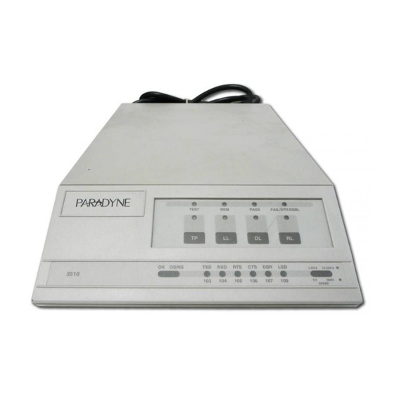
(DTE) to the digital network. By selecting the appropriate data rates, you can also use Model 3510 or Model 3511 DSUs as local area data sets (LADS). Figure 1-1. Model 3510 DSU... -
Page 14: Model 3511 Dsu And Rear Connector Plates
COMSPHERE 3500 Series Data Service Units Both the Model 3510 and Model 3511 DSUs are compatible with earlier DATAPHONE II 2500 Series and 2600 Series DSUs, and they incorporate a number of enhancements. Model 3510 supersedes the 2556B, 2596B, 2656B, and 2696B DSUs. Model 3511 supersedes the 2556A and 2596A DSUs. -
Page 15: Features
Features The Model 3510 and Model 3511 DSUs contain the following standard features: Switch-selectable data rates of 2400, 4800, 9600, 19,200, 38,400, 56,000, and 64,000 bps. Compatibility with the channel interface defining DDS service in AT&T Technical Reference 62310. Additional option switch settings, allowing 19,200 bps loop operation at levels of –10 dBm, 0,... -
Page 16: Technical Specifications
COMSPHERE 3500 Series Data Service Units Technical Specifications Table 1-1 lists the technical specifications for Model 3510 and Model 3511 DSUs. Technical Specifications for Model 3510 and Model 3511 DSUs Technical Specifications APPLICATION DDS DATA RATE MODULATION LINE REQUIREMENTS LADS... - Page 17 Technical Specifications for Model 3510 and Model 3511 DSUs Technical Specifications PHYSICAL DIMENSIONS Model 3510 Height Width Depth Weight Model 3511 Height Width Depth Weight Rear Connector Plate Height Width Depth Weight DTE INTERFACES NETWORK INTERFACE APPROVALS FCC Part 15...
-
Page 18: Equipment Warranty And Support
Via the Internet: Visit the Paradyne World Wide Web site at http://www.paradyne.com Via Telephone: Call our automated call system to receive current information via fax or to speak with a company representative. — Within the U.S.A., call 1-800-870-2221 — Outside the U.S.A., call 1-727-530-2340 July 1999 3510-A2-GN32-70... -
Page 19: Principles Of Operation
DSUs and a Model 3510 DSU at the remote end. For 2600 Series diagnostic multipoint networks, the Model 3510 DSU can also be installed as a tributary DSU. In this application, the standalone Model 3510 DSU at the tributary end is functionally equivalent to a DATAPHONE II 2600 Series DSU, and no additional support is needed. -
Page 20: Example Point-To-Point And Multipoint Networks
COMSPHERE 3500 Series Data Service Units Figure 2-1. Example Point-to-Point and Multipoint Networks July 1999 3510-A2-GN32-70... -
Page 21: Dsu Compatibility
DSU Compatibility For primary channel communication, the standalone Model 3510 and the carrier-mounted Model 3511 DSUs are fully compatible with all Paradyne digital products that operate at the same speed and power level. Point-to-point and multipoint configurations are not limited to connections between 3500 Series DSUs; many other combinations of equipment are possible. -
Page 22: 2600 Series Compatibility
(NMS) sends messages to a 2600 Series shared diagnostic unit (SDU) which, in turn, causes a 2600 Series DATAPHONE II DSU to send the above commands to a tributary Model 3510 DSU via the digital network. Local Area Data Set (LADS) -
Page 23: Operation
Use the controls and indicators on the standalone and carrier-mounted DSUs to operate the units and control the network. The faceplate on both the Model 3510 and Model 3511 contains 18 light-emitting diodes (LEDs) and four pushbutton switches. -
Page 24: Series Indicators And Switches
TEST and REM indicators will also be lit). TEST OK OS/NS TXD RXD RTS CTS DSR LSD 103 104 105 106 107 Figure 3-1. Model 3510 Faceplate Table 3-1 (1 of 3) 3500 Series Indicators and Switches Definition This green indicator lights when the DSU is connected to the digital network or LADS and is operating normally. - Page 25 Fail (3511) – This indicator rapid flashes during Test Pattern when errors are detected. DSBL (3510) – Indicator lights if the DSU has been disabled. STR (3510) – Indicator slow flashes when a streaming terminal alarm condition exists.
- Page 26 9600 bps. This green indicator flashes when the DSU has been configured for a data rate of 19,200 or 38,400 bps. If the indicator is ON, the DSU has been configured at 56,000 bps or 64,000 bps. July 1999 Function 3510-A2-GN32-70...
-
Page 27: Model 3511 Faceplate
DSU status indicators, the four pairs of test switches and test indicators, and the six DTE interface indicators for both the 3510 and 3511 DSUs. The status indicators are always active as long as the DSU is functioning properly and has power; however, you can choose to disable the four test switches via a DSU option in order to prevent unauthorized testing. -
Page 28: Device Test Diagram
(Figure 3-3). The receiver then passes the test message it receives to the comparator. The comparator checks the received message for errors. Errors cause the faceplate Dsbl/Fail (3511) or FAIL/STR/DSBL (3510) indicator to flash. At the conclusion of the test, the PASS or FAIL indicator lights. -
Page 29: Device Test Procedure
4. Press the LL test switch. During this test, TXD, LSD, and RXD DTE interface indicators monitor internal versions of the corresponding interface lead. 3510-A2-GN32-70 Device Test Results If, at the conclusion of the Device Test, the PASS indicator is lit, then the DSU has passed the test and has a very high probability of not being the source of trouble. -
Page 30: Digital Test (Point-To-Point) Diagram
DSU. The test does not require an attendant at the remote DSU location. When the test is completed, press the RL and TP test switches to return the DSU to normal. July 1999 3510-A2-GN32-70... -
Page 31: Digital Test (Point-To-Point) Procedure
4. Press the RL test switch. During this test, TXD, LSD, and RXD DTE interface indicators monitor internal versions of the corresponding interface lead. 3510-A2-GN32-70 Point-to-Point Digital Test Results If the FAIL indicator remained Off for the entire test interval, the Digital Test has passed and no problems have been detected in either the DSUs or the network. -
Page 32: Digital Test (Multipoint) Diagram
To start the test, press the TP test switch at local DSU and the DL test switch at the remote DSU. Look for FAIL indicator flashes during the test. To end the test, press the local DSU TP and the remote DSU DL test switches. July 1999 3510-A2-GN32-70... -
Page 33: Digital Test (Multipoint) Procedure
DL test switch be pressed. During this test, the TXD, LSD and RXD DTE interface indicators monitor internal versions of the corresponding interface lead. 3510-A2-GN32-70 Multipoint Digital Test Results If the FAIL indicator remained Off for the entire test interval, the Digital Test has passed and no problems have been detected in either the DSUs or the network. - Page 34 LL test switch. Local Loopback Procedures Follow the procedure in Table 3-5 perform a Local Loopback – DTE Test Message. Local Loopback Results For proper operation, the test message should be received error free. July 1999 Table 3-6 3510-A2-GN32-70...
-
Page 35: Local Loopback – Dte Test Message Procedure
Pin 18 of the EIA interface or Pin LL of the V.35 interface will not function unless straps S3-3 and S3-4 are enabled. DSR EIA output and the indicator goes Off during LL unless strap S5-5 (DSR always ON) is enabled. 3510-A2-GN32-70 Table 3-5 LL indicator lights, TEST indicator flashes. After about 6 seconds, TEST indicator remains ON. -
Page 36: Troubleshooting
COMSPHERE 3500 Series Data Service Units Channel Loopback The Model 3510 and 3511 DSUs perform a Channel Loopback test whenever they detect reversal of the sealing current in the local loop. In addition, these DSUs connected to subrate or 56 kbps DDS local loops respond... -
Page 37: Out-Of-Service Condition Troubleshooting Flowchart
Operation Figure 3-8. Out-of-Service Condition Troubleshooting Flowchart 3510-A2-GN32-70 July 1999 3-15... -
Page 38: No Signal Condition Troubleshooting Flowchart
COMSPHERE 3500 Series Data Service Units Figure 3-9. No Signal Condition Troubleshooting Flowchart 3-16 July 1999 3510-A2-GN32-70... -
Page 39: Streaming Terminal Condition Troubleshooting Flowchart
Operation Figure 3-10. Streaming Terminal Condition Troubleshooting Flowchart 3510-A2-GN32-70 July 1999 3-17... -
Page 40: 2600 Series Dsu Emulation
REM indicator slow flash DL indicator ONTEST indicator ON Transmit Test Pattern: This command is used to cause a 3510 tributary DSU to transmit its test pattern. If the other end is also placed in Test pattern, it is possible to conduct an End-to-End Test and isolate marginal troubles to the send or receive direction. -
Page 41: Installation
Section 60 of the Canadian Electric Code, Part 1, in Canada. Model 3510 DSUs Model 3510 DSUs must be installed within 6 feet of a grounded ac outlet controlled by a circuit breaker and capable of furnishing 90 to 132 Vac, 0.07 amps at 117 Vac. -
Page 42: Important Safety Instructions
Read and follow all warning notices and instructions marked on the DSU or included in this guide. If you have a standalone Model 3510 DSU, do not attempt to service it yourself, as removal of the case will expose you to dangerously high voltage points or other risks. -
Page 43: Installation Procedures
Model 3510 DSUs and carrier-mounted Model 3511 DSUs. Refer to the appropriate section. Model 3510 DSUs Physical installation of the Model 3510 consists of unpacking the DSU and placing it in its planned location. Electrical installation requires the following procedure. -
Page 44: Model 3510 Dsu, Rear Panel
FCC or Bell Canada rules, and for information required to obtain the desired service from the telephone company. The Model 3510 DSU’s rear panel contains a miniature universal service ordering code (USOC) type RJ48S jack for connecting your DSU to the... - Page 45 4. If the DSU has been repaired, verify and change the strap settings, as necessary. 5. Continue with Steps 4 through 11 of the installation procedure. Replacement of the Model 3510 DSU is complete. 3510-A2-GN32-70 Model 3511 DSUs This section includes the installation procedures for the...
-
Page 46: Front View Of The Comsphere 3000 Series Carrier
COMSPHERE 3500 Series Data Service Units 496-12291-04 Figure 4-2. Front View of the COMSPHERE 3000 Series Carrier July 1999 3510-A2-GN32-70... -
Page 47: Rear View Of The Comsphere 3000 Series Carrier
DSU. Figure 4-3. Rear View of the COMSPHERE 3000 Series Carrier 3510-A2-GN32-70 3. Loosely fasten the screw attached to the rear connector plate, allowing for slight adjustment that may be needed when installing the DSU. -
Page 48: Model 3511 Dsu Installation And Circuit Pack Lock
If using an EIA-232-D interface cable, connect the EIA-232-D cable to the top DTE connector on the rear connector plate. If using a V.35 interface cable, proceed to the next procedure. Installation of the DSU and its rear connector plate is complete. July 1999 3510-A2-GN32-70... - Page 49 2. Connect the 34-pin end of the V.35 adapter to the DTE’s V.35 interface cable. Tighten the screws on both sides of the connector. Figure 4-5. Model 3511 DSU V.35 Adapter Plug Installation 3510-A2-GN32-70 Installation of the V.35 interface cable is complete. For the V.35 connector, the recommended maximum distance between a DTE and a DSU is nominally 1000 feet.
- Page 50 Return the DSU to the company per instructions included in the Equipment Warranty and Support Chapter 1. Removal of the Model 3511 DSU is complete. July 1999 4-4). Open the latch. section of 3510-A2-GN32-70...
-
Page 51: Local Area Data Set (Lads) Operation
The straps also allow you to configure either type of DSU (Model 3510 or 3511) as a LADS for connection to 4-wire metallic circuits. Table 4-2... -
Page 52: Model 3510 Dsu Strap Access
COMSPHERE 3500 Series Data Service Units For the Model 3510 DSU, the straps are concealed behind the faceplate as shown in Figure 4-6. To remove the faceplate to change the hardware straps: " Procedure 1. With your thumbs under the edge of the front bezel, firmly press upward to lift the bezel from the tabs securing it in place. - Page 53 Figure 4-7 shows the physical location of the straps on a Model 3511 DSU. The straps are not concealed, as they are on the Model 3510 DSU, and should be set before the DSU is installed in a COMSPHERE 3000 Series Carrier.
-
Page 54: Dsu Strap Default Settings
COMSPHERE 3500 Series Data Service Units Figure 4-8. DSU Strap Default Settings 4-14 July 1999 3510-A2-GN32-70... -
Page 55: Data Rate (Speed) Selection (Switch S2) For Model 3510 And Model 3511 Dsus
Installation Figure 4-9. Data Rate (Speed) Selection (Switch S2) for Model 3510 and Model 3511 DSUs 3510-A2-GN32-70 July 1999 4-15... -
Page 56: Timing Signal Source Selection (Switch S1)
COMSPHERE 3500 Series Data Service Units Figure 4-10. Timing Signal Source Selection (Switch S1) Figure 4-11. S1 Default Settings, Model 3510 and Model 3511 DSUs 4-16 July 1999 3510-A2-GN32-70... -
Page 57: S2 Default Settings, Model 3510 And Model 3511
Installation Figure 4-12. S2 Default Settings, Model 3510 and Model 3511 Figure 4-13. S3 Default Settings, Model 3510 and Model 3511 3510-A2-GN32-70 July 1999 4-17... -
Page 58: S5 Default Settings, Model 3510 And Model 3511
S1–3 S1–4 S1–5 S1–6 F = Front R = Rear Selections are the same for Model 3510 and Model 3511 unless otherwise noted. 4-18 Table 4-3 (1 of 3) Function Selects source of timing signals (see Selects source of timing signals (see... - Page 59 S3–6 S4–1 S4–2 S4–3 S4–5 S4–6 F = Front R = Rear Selections are the same for Model 3510 and Model 3511 unless otherwise noted. 3510-A2-GN32-70 Table 4-3 (2 of 3) Function Select data rate (see Table 4-5) Disables streaming terminal function...
-
Page 60: Timing Signal Source Selection For Both Model 3510 And Model 3511
— S5–5 S5–6 F = Front R = Rear Selections are the same for Model 3510 and Model 3511 unless otherwise noted. Timing Signal Source Selection for Both Model 3510 and Model 3511 S1–1 F = Front R = Rear... -
Page 61: Data Rate Selection For Both Model 3510 And Model 3511
Data Rate Selection for Both Model 3510 and Model 3511 S2–1 S2–2 S2–3 F = Front R = Rear NOTE: Other data rate combinations should not be used. Network Network Address F = Front R = Rear 3510-A2-GN32-70 Table 4-5 S2–4... - Page 62 COMSPHERE 3500 Series Data Service Units Network Network Address Address F = Front R = Rear 4-22 Table 4-6 (2 of 4) Model 3510 DSU S4 Selection Switch S4 Selection July 1999 3510-A2-GN32-70...
- Page 63 Network Network Address Address F = Front R = Rear 3510-A2-GN32-70 Table 4-6 (3 of 4) Model 3510 DSU S4 Selection Switch S4 Selection July 1999 Installation 4-23...
-
Page 64: Dsu Strap Setting Descriptions
4-24 Table 4-6 (4 of 4) Model 3510 DSU S4 Selection Switch S4 Selection S1-4: DSR Normal during Local Loopback – DSR ON during Local Loopback. When enabled, this strap forces the DSR lead ON during a Local Loopback. This allows DTEs that rely on DSR being on to send test messages to the DSU. - Page 65 Signal Ground to Frame Ground, or separates Signal Ground from Frame Ground. (This strap only applies to Model 3510 DSUs. For the Model 3511 DSUs, the strap is on the UAC.) S5-2: Test Mode Indication – When this strap is enabled, Pin 25 in the EIA-232-D interface of the DSU is ON to indicate when the DSU is in a test condition;...
-
Page 66: Alarm Output Installation
RXD lead except when the DSU is involved in a test or has been disabled. NOTE This strap is only required for Model 3510 tributary DSUs installed in DATAPHONE II 2600 diagnostic networks. For all other applications, Diagnostic Message Clamping should be disabled. -
Page 67: Connector Pins
..............Digital Network Connectors A keyed, 8-pin modular type RJ48S jack on the rear of the Model 3510 connects the DSU to the digital network. Figure A-1 shows the RJ48S plug. Pin assignments are listed and described in Table A-1. -
Page 68: A-2 Rj48T Digital Network Connector Pins (50-Pin) For The Comsphere 3000 Series Carrier (Model 3511)
2 or 10 3 or 11 4 or 12 5 or 13 6 or 14 7 or 15 8 or 16 Standalone (Model 3510) Canadian Adapter Cable Pins RJ48S Circuit Name Table A-2 Receive Circuits Table A-3 — Not used... -
Page 69: A-4 Model 3510 And 3511 Dsu 25-Pin Eia-232-D/V.24 Connector Pins
EIA-232-D/V.24 Connector The Model 3510 DSU’s rear panel and the Model 3511 DSU’s rear connector plate includes a 25-pin EIA-232-D/V.24 connector for connection to the DTE. Pin assignments are listed and described in Table A-4. Model 3510 and 3511 DSU 25-Pin EIA-232-D/V.24 Connector Pins... -
Page 70: A-2 Model 3511 Dsu Rear Connector Plate
COMSPHERE 3500 Series Data Service Units Model 3510 DSU 34-Pin V.35 Connector Pins V.35 Pins Identifier P, S R, T — — U, W Y, AA V, X Figure A-2. Model 3511 DSU Rear Connector Plate Table A-5 ITU-T Identifier... - Page 71 34-Pin Connector on Rear Connector Plate V.35 Adapter 24, 11 23, 22 15, 2 16, 3 14, 1 3510-A2-GN32-70 99-16294 Figure A-3. V.35 Adapter Plug Table A-6 Signal Ground Request-to-Send (RTS) Clear-to-Send (CTS) Data Set Ready (DSR) Received Line Signal Detect (RLSD)
- Page 72 COMSPHERE 3500 Series Data Service Units July 1999 3510-A2-GN32-70...
- Page 73 The chart number is located in the upper left-hand corner of each segment of Figure B-1, above the name of the test. 3510-A2-GN32-70 Timing During Testing For each test, find the appropriate timing column down through the steps in the test to determine the source of (Figure B-1) show timing changes.
- Page 74 COMSPHERE 3500 Series Data Service Units Figure B-1. DSU Timing Chart (1 of 2) July 1999 3510-A2-GN32-70...
- Page 75 Timing During Testing Figure B-1. DSU Timing Chart (2 of 2) 3510-A2-GN32-70 July 1999...
- Page 76 COMSPHERE 3500 Series Data Service Units July 1999 3510-A2-GN32-70...
- Page 77 Rear Connector Plate – 25-Pin EIA-232/25-Pin ITU-T V.35 V.35 Adapter Cable V.35 Adapter Plug Modular 8-pin to 8-pin (RJ45S) Network Cable Modular 8-pin to 6-pin Network Cable (for the Model 3510 in Canada) COMSPHERE 3000 Series Carrier, Installation Manual 3510-A2-GN32-70 Equipment List Feature Number...
- Page 78 Standalone (Model 3510 DSU) CCA Carrier-mounted (Model 3511 DSU) – modular CCA Rear Connector Plate – 25-Pin EIA-232/25-Pin CCITT V.35 AC Power Cord (included with Model 3510) V.35 Adapter Modular 8-pin to 8-pin (RJ45S) Network Cable Modular 8-pin to 6-pin Network Cable...
- Page 79 (DL) Electronic Industries Association (EIA) ITU-T 3510-A2-GN32-70 Glossary A framework containing slots for circuit cards. The 3000 Series Carrier fits in a 19- or 23-inch rack and accommodates up to 16 DSUs. A signal issued by a DSU to indicate that it is connected to the digital network and is ready to accept data.
- Page 80 A test that generates a digital test pattern and verifies that the DSU is receiving the same pattern. A serial stream of digital information that is transmitted by a DTE. Generic telephone company service ordering codes. July 1999 3510-A2-GN32-70...
- Page 81 2600 Series DSU, emulation, 3-18 2600 Series DSU compatibility, 2-4 3000 Series Carrier front view, 4-6 rear view, 4-7 Abort Test command, 3-18 adapter cable connector pins, standalone (Model 3510), Canadian, A-2 alarm output installation, 4-26 application, 1-4 approvals, 1-5 Bell Canada approval, 1-5...
- Page 82 Local Loopback, 3-12 Digital Loopback, B-1 (remote), S1 description, 4-24 digital network connection, 4-10 connectors, A-1 interface (RJ48T), pin assignments (Model 3511), RJ48S connector pins (Model 3510), A-1 Digital Test, B-1 (point-to-point), diagram, 3-8 command, 3-18 multipoint, 3-10 diagram, 3-10 procedure, 3-11...
- Page 83 3-11 test results, 3-11 network address, S4 description, 4-25 configurations, 2-1 connector RJ48S pins (Model 3510), A-1 RJ48T pins (Model 3511), A-2 digital connection, 4-10 interface, 1-5 multipoint, DATAPHONE II, 2-4 No Signal condition, flowchart, 3-16 OK indicator, 3-2...
- Page 84 1-5 instructions, 4-2 scrambler, S3 description, 4-25 shock and vibration, 1-4 signal ground-frame ground, S5 description, 4-25 specifications, technical, 1-4 standalone (Model 3510), Canadian adapter cable pins, static electricity discharge, 4-5 storage temperature, 1-4 strap access, Model 3510, 4-12 location...
- Page 85 (Switch S1), strap selection, 4-16, 4-20 TP indicator, 3-3 Transmit Test Pattern command, 3-18 troubleshooting, 3-14 TXD indicator, 3-3 UL approval, 1-5 3510-A2-GN32-70 V.35 adapter, A-5, C-1, C-2 connector pins, A-5 installation, 4-9 connector, A-3 DTE interface (S3), 4-25...
Need help?
Do you have a question about the Comsphere 3510 and is the answer not in the manual?
Questions and answers