Table of Contents
Advertisement
Available languages
Available languages
Quick Links
Before installing the device, read the instructions
carefully. The installer and the final user must
observe the laws and standards, and make sure
that they comply with relative local regulations. The
device is assembled in compliance with existing
community laws and the Manufacturer declines any
liability in case of damage caused by incorrect use
or use in conditions differing from those indicated
on the nameplate and in these instructions.
Symbols and danger indications as listed
below are present in this instruction manual.
WARNING:
•
If these instructions are not observed, personal
injuries or death brought by electric shock may occur.
•
This symbol means that an action must be taken.
•
If these indications are not followed, damage or
failure of the device may occur.
•
Suggestions and tips recommended to facilitate
the work.
1. PRODUCT DESCRIPTION
The device is an electronic flow switch for pumps servicing
hydraulic systems.
There is a minimum flow required for proper functioning.
2. APPLICATIONS
The device finds its application in typical water supply systems
and rainwater systems in residences, buildings, gardening,
agriculture, and industry.
FLOW PRESS
Device for control and protection
INSTALLATION AND FUNCTIONING INSTRUCTIONS
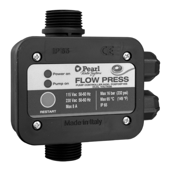
3. TECHNICAL DATA
VOLTAGE
ACCEPTABLE VOLTAGE
FLUCTUATION
FREQUENCY
MAXIMUM CURRENT
MAXIMUM POWER
MAXIMUM RUNNING
PRESSURE
MAXIMUM RUNNING
TEMPERATURE
DEVICE
PROTECTION DEGREE
DIMENSIONS
fig.5
4. PUMPED LIQUIDS
The product is suitable for clean water, non-aggressive and
non-explosive liquids, without solid parcels or fiber potentially
able to affect the device mechanically or chemically.
In the presence of aggressive liquids, the product may be
provided, on request, with a flow valve in AISI 306 instead of the
standard flow valve in brass.
of the electric pump
115/230 Vac
+/- 10%
50-60 Hz
8 A
0,55 kW (0,75 HP) 1,1 kW
(1,5 HP)
16 bar (1,6 MPa)
65°C
1C
IP 65
Fig. 5
Advertisement
Table of Contents

Related Manuals for Pearl FLOW PRESS


Summary of Contents for Pearl FLOW PRESS
- Page 1 FLOW PRESS Device for control and protection of the electric pump INSTALLATION AND FUNCTIONING INSTRUCTIONS 3. TECHNICAL DATA Before installing the device, read the instructions carefully. The installer and the final user must VOLTAGE 115/230 Vac observe the laws and standards, and make sure that they comply with relative local regulations.
-
Page 2: Control Panel
5. CONTROL PANEL fig.3 The green light lit up indicates that the POWER ON device is energized (fig.1/a). The yellow light lit up indicates that the PUMP ON pump is running (fig.1/b). min. 20 cm Flow Reset button to push in case of RESTART anomaly (fig.1/c). -
Page 3: Automatic Restart
To reset the system, keep the restart button pushed until the Pumps with power of more than the indicated in paragraph water flows from the tap. “Technical Characteristics’’ of this manual can be connected through a contactor (fig.4/b). In case of a temporary power outage, the device restarts fig.4 automatically when the power returns. -
Page 4: Instrucciones De Instalación Y Funcionamiento
FLOW PRESS Dispositivo de control y protección de la electrobomba INSTRUCCIONES DE INSTALACIÓN Y FUNCIONAMIENTO 3. FICHA TÉCNICA Lea atentamente las instrucciones antes de instalar el aparato.Tanto el instalador como el usuario final FUENTE DE ALIMENTACIÓN 115/230 Vac deben seguir las instrucciones cuidadosamente de acuerdo con los reglamentos, normas y leyes VARIACIONES DE TENSIÓN... -
Page 5: Conexiones Eléctricas
5. PÁNEL DE CONTROL fig.3 La luz verde encendida indica que el POWER ON aparato está en funcionamiento (fig.1/a). La luz amarilla encendida indica que la PUMP ON bomba está en funcionamiento (fig.1/b). min. 20 cm Flow El botón de reinicio debe pulsarse en RESTART caso de avería (fig.1/c). - Page 6 Para reiniciar el sistema, mantenga pulsado el botón de reinicio Las bombas con una potencia superior a la indicada en la hasta que salga agua del grifo. “Ficha técnica” de este manual pueden conectarse al aparato a través de un interruptor de control remoto (fig.4/b). En caso de apagón temporal, el aparato se reinicia fig.4 automáticamente en cuanto vuelva la corriente.
Need help?
Do you have a question about the FLOW PRESS and is the answer not in the manual?
Questions and answers