Table of Contents

Related Manuals for Samsung MIM-F10N


Summary of Contents for Samsung MIM-F10N
- Page 1 DVM CHILLER Installation manual FCU Interface Module MIM-F10N • Thank you for purchasing this Samsung Product. • Before operating this unit, please read this Insatallation manual carefully and retain it for future reference.
-
Page 2: Safety Precautions
Safety precautions This installation manual explains how to install a FCU interface module that is connected to a Samsung FCU KIT. Please read this manual thoroughly before installing the product. (Please refer to appropriate installation for any optional product installation.) WARNING Hazards or unsafe practices that may result in severe personal injury or death. -
Page 3: For Operation
Do not install the product in a place where flammable gas leaks or if there is possible chance of leakage. • Do not install the product in a place where it will be exposed to oil or vapor etc. • If the product is used in a place where it is exposed to oil, vapor or sulphur dioxide, parts of the product may get dam- aged or product may function abnormally. - Page 4 FCU interface module installation Accessories FCU interface DC power Communication Installation Item Case Cable tie Screw (M4) module cable (12 V) cable Manual Shape Diagram of connection between a FCU interface module and FCU KIT Fix the FCU interface module case at fixing point of FCU KIT by 1 screw. Attach FCU interface module to the case and connect power and communication cable.
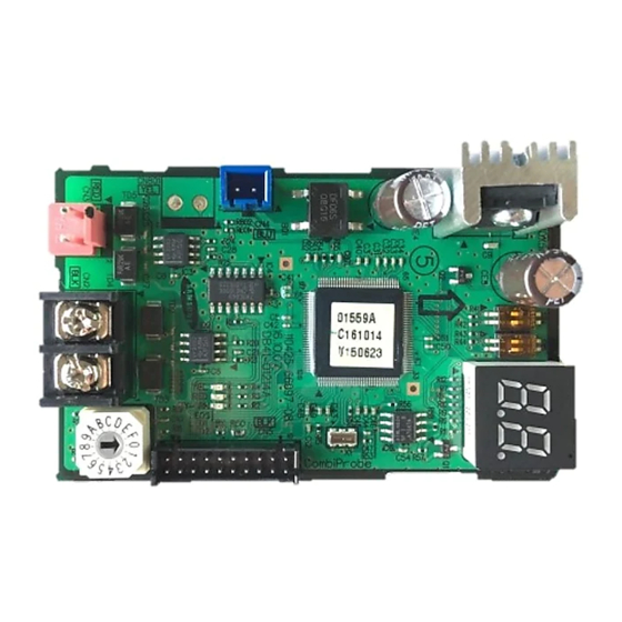
- Page 5 Connecting FCU KIT • Connect DC power cable connector (Blue) to CN12 of FCU KIT MAIN PBA. • Communication cable (Red) is ring type. Connect the cable to F1, F2 terminal of FCU KIT MAIN PBA. FCU interface module Connect with upper level controller FCU KIT CAUTION •...
- Page 6 FCU interface module installation Set the address of FCU interface module. • The address of each FCU interface module should be set differently. CAUTION • The cable length between the upper controller and the farthest FCU interface module should be within 1000 m. •...
- Page 7 About setting the main address manually and installation condition Manual address No function Automatic address • Automatic address: Address of the interface module is assigned randomly. • Manual address: Address of the interface module is assigned by address switch of the FCU interface module. NOTE •...
-
Page 8: Checking Operation
Checking operation LED Display to 10 minutes. communication, Y-GRN LED will blink. (Please wait until the communication between and FCU interface module and the FCU KIT becomes normal.) communication, RED LED will blink. NOTE • YEL LED is not in use. - Page 9 7-SEGMENT indication • Exmaple of program code: 17 89 A3 16 Then tracking of FCU KIT will be on progress, and will be indicated. After tracking is done, communicating address of FCU KIT will be indicated in order when the communication is normal.
- Page 10 Memo...
- Page 12 (For India only) For more information on safe disposal and recycling, visit our website www.samsung.com/in/support or contact our Helpline For correct disposal of this product, please visit http://www.samsung.com/weee.pdf À...
Need help?
Do you have a question about the MIM-F10N and is the answer not in the manual?
Questions and answers