
Related Manuals for Samsung MIM-B16


Summary of Contents for Samsung MIM-B16
- Page 1 INSTALLATION MANUAL MIM-B16 (Pulse Input Module) DB98-32320A(1) MIM-B16_PIM_IM_E 32320-1.indd 2010-05-20 ソタネト 7:19:08...
-
Page 2: Safety Precautions
Safety Precautions This installation manual describes how to install the PIM. For installation of other optional accessories, refer to the appropriate installation manual. R ead carefully this installation manual before WARNING installation and check if the PIM is installed correctly after installation. -
Page 3: Table Of Contents
Contents AFETY RECAUTIONS .............. CCESSORIES .................. IEWING THE ARTS ................ RODUCT IMENSIONS ..............PIM S YSTEM RCHITECTURE ............ NSTALLING THE .............. ETTING THE ................PIM M ESCRIPTION ............. MIM-B16_PIM_IM_E 32320-1.indd 2010-05-20 ソタネト 7:18:42... -
Page 4: Accessories
Accessories Make sure you have each item. Supplied items may vary depending on your country or service provider. Item Adapter Power cable M4 x16 Screw Quantity Shape Installation Cable tie manual The PIM must be installed by a trained installer. ... -
Page 5: Viewing The Parts
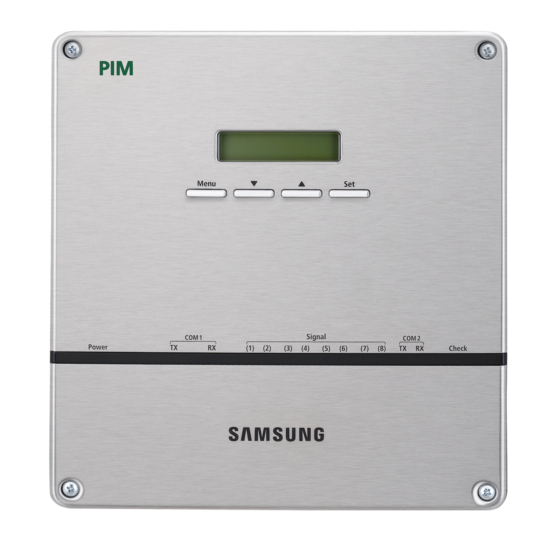
Viewing the Parts Main Parts PIM Exterior LCD Display Shows current time and power consumption by channel. Various menus will be displayed depending on button input. LCD Operation button There are 4 buttons [Menu, ▼(Down), ▲(Up), Set] and you can access, move and check the menu. - Page 6 Viewing the Parts (Continued) Main Parts PIM Cable Connection Part Pulse input terminal Pulse input terminal RS485 communication terminal (Channel 1~4) (Channel 5~8) (COM1, COM2) Cable tie groove Power terminal Reset button Name Description Pulse input Terminal that the pulse from watt-hour meter is inputted terminal (Channel1~Channel8) (CH1~CH8)
-
Page 7: Product Dimensions
PIM Interior Display board 20-pin cable Main board 40-pin cable Sub board Product Dimensions 64.80 (Unit : mm) MIM-B16_PIM_IM_E 32320-1.indd 2010-05-20 ソタネト 7:18:45... -
Page 8: Pim System Architecture
PIM System Architecture DMS or DMS2 Centralized controller R2 R1 R2 R1 R2 R1 R2 R1 R2 R1 R2 R1 R2 R1 R2 R1 Interface Pulse input module R1 R2 R1 R2 R1 R2 R1 R2 ROOM 0 ROOM 1 ROOM 2 Watt-hour meter... -
Page 9: Installing The Pim
Installing the PIM Installing the PIM on the Wall Separate the installation plate on the rear side of PIM. Fix the installation plate on the wall using 4 screws. Hang the PIM on the groove which is on the top of the installation plate. - Page 10 Installing the PIM (Continued) Connecting Watt-hour meter, PIM and DMS Connecting Watt-Hour meter and PIM Unfasten the 2 screws on the bottom of the PIM front cover. Hold the bottom 2 sides of the PIM and push downwards to slide open the cover. Connect the adapter to the power terminal.
- Page 11 Connectable Watt-hour meter with PIM Watt-hour meter without Separate External Output I f the pulse constant(Wh/Pulse) value which is converted from the value of Pulse/Wh is an integer, connection is possible. e.g. Pulses per kWh : 1,000 converted to 1Wh/Pulse, Connection is possible! e.g.
- Page 12 Installing the PIM (Continued) Connecting PIM to DMS or DMS2 Connect ‘COM1’ terminal of PIM and DMS or DMS 2 terminal block with communication cable. DMS2 Connect Connect Connect communication communication communication cable cable cable Pay special attention about the polarity when connecting RS485 communication. (A of PIM of DMS, B of PIM B of DMS)
- Page 13 W hen execute tracking with PIM which connected to DMS and DMS2(ver 2.1.1 or previous version) Displays the number of SIM which included the number of connected PIM For the further information about tracking, refer to the DMS user manual(page 30). ...
- Page 14 Installing the PIM (Continued) I f PIM is connected to DMS2(ver 2.1.2 or later version), PIM setting through DMS2 web is possible. MIM-B16_PIM_IM_E 32320-1.indd 2010-05-20 ソタネト 7:18:50...
- Page 15 Installing more than 2 PIM Units to 1 DMS Unfasten the 2 screws on the top of the PIM. Hold the top 2 sides of the PIM and pull it the cover upwards to open the cover. Set the PIM address using rotary switch of main PCB. (Default setting: 10H) ...
-
Page 16: Setting The Pim
Setting the PIM Setting the PIM(Mandatory) It is mandatory when you connect watt-hour meter and PIM. Setting the Password 2.1Password Set your P/W Password Set : : : : Main menu 2. Configuration 2.1 Password. Default : 0000 For the further information, refer to page 20. Setting the Date/Time Set Current Date Set Current Time... -
Page 17: Pim Menu Description
PIM Menu Description Menu Configuration Normal Display 1. Monitoring 1.1 PIM Address 1.2 Option SW Current Time 2. Configuration 2.1 Password CH1: 00000.0kWh 2.2 Wh/Pulse CH2: 00000.0kWh 2.3 Pulse Width CH8: 00000.0kWh 2.4 PIM Time Displayed repeatedly 2.5 Channel 2.6 KWh Set 2.7 KWh Clear 3. - Page 18 PIM Menu Description (Continued) Normal Display PIM Address:10H Ver:DB91-01128A When the power is connected, current PIM address and software version will be displayed. Example display: PIM address 10H Software version DB91-01128A “Address:10H” is an example. It is subject to change according to the setting. CH1:00000.0kWh CH2:00000.0kWh Power consumption of pulse input CH1~CH8 will be displayed in order.
- Page 19 Monitoring Menu PIM Address Main Menu 1.Monitoring Access to main menu by pressing the [Menu] button from the normal display. Then select ‘1.Monitoring’ by pressing the [Set] button. 1.Monitoring 1.1 PIM Address 1.1 PIM Address Address:10H To check the PIM address, press the [Set] button when ‘1.1PIM Address’ appears. Note ...
- Page 20 PIM Menu Description (Continued) Configuration menu Setting the Password Y ou should enter the password to use Configuration menu. Password Set Main Menu 2.Configuration Access to main menu by pressing the [Menu] button from the normal display. Then select ‘2.Configuration’ by pressing the [], [] buttons, and press the [Set] button.
- Page 21 Password Reset Main Menu 2.Configuration Access to main menu by pressing the [Menu] button from the normal display. Then select ‘2.Configuration’ by pressing the [], [] buttons, and press [Set] button. Enter your P/W 0:0:0:0 Enter the password using the [], [] buttons and press the [Set] button. ...
- Page 22 PIM Menu Description (Continued) Setting the Wh/Pulse Y ou can set the Wh/Pulse value of watt-hour meter which connected to each channel. Main Menu 2.Configuration Access to main menu by pressing the [Menu] button from the normal display. Then select ‘2.Configuration’ by pressing the [], [] buttons, and press the [Set] button.
- Page 23 Setting the Pulse Width Y ou can set the pulse width according to the specification of watt-hour meter which connected to each channel. Main Menu 2.Configuration Access to main menu by pressing the [Menu] button from the normal display. Then select ‘2.Configuration’...
- Page 24 PIM Menu Description (Continued) Setting the PIM Time Date setting Main Menu 2.Configuration Access to main menu by pressing [Menu] button from the normal display. Then select ‘2.Configuration’ by pressing the [], [] buttons, and press [Set] button. Enter your P/W 0:0:0:0 Enter the password using the [], [] buttons and press the [Set] button.
- Page 25 Time setting Main Menu 2.Configuration Access to main menu by pressing [Menu] button from the normal display. Then select ‘2.Configuration’ by pressing the [], [] buttons, and press [Set] button. Enter your P/W 0:0:0:0 Enter the password using the [], [] buttons and press the [Set] button. ...
- Page 26 PIM Menu Description (Continued) Setting the Enable/Disable Status of Channel E nable/Disable the 8 pulse input channels. Main Menu 2.Configuration Access to main menu by pressing the [Menu] button from the normal display. Then select ‘2.Configuration’ by pressing [], [] buttons, and press the [Set] button.
- Page 27 Setting the Initial Value of Watt-hour meter (KWh) E xisting usage can be reflected by setting the initial value according to the watt-hour meter which connected to each channel. Main Menu Enter your P/W 2.Configuration 0:0:0:0 Access to main menu by pressing the [Menu] button from the normal display. Then select ‘2.Configuration’...
- Page 28 PIM Menu Description (Continued) Initializing the Power Consumption by Channel Main Menu 2.Configuration Access to main menu by pressing the [Menu] button from the normal display. Then select ‘2.Configuration’ by pressing the [], [] buttons, and press the [Set] button. Enter your P/W 0:0:0:0 Enter the password the [], [] buttons and then press the [Set] button.
- Page 29 Check Menu Pulse Input Status Check Y ou can check the status of pulse which is input to each channel. Main Menu 3.Check Access to main menu by pressing the [Menu] button from the normal display. Then select ‘3. Check’ by pressing the [], [] buttons, and press [Set] button. 3.Check 3.1 Pulse Input Select ‘3.1 Pulse Input’...
- Page 30 PIM Menu Description (Continued) Check the RS485 Circuit of PIM itself for Test or Service Y ou can check if the RS485 circuit is normal when you have doubt the main board. B efore checking, connect COM1 and COM2 terminal with wire ...
- Page 31 Checking the Pulse Width Setting Error I t checks if the pulse width setting for each channel and the pulse width of actually connected watt-hour meter are same or not. Main Menu 3.Check Access to main menu by pressing the [Menu] button from the normal display. Then select ‘3.
- Page 32 MIM-B16_PIM_IM_E 32320-1.indd 2010-05-20 ソタネト 7:19:08...
Need help?
Do you have a question about the MIM-B16 and is the answer not in the manual?
Questions and answers