Lincoln Electric IDEALARC DC-1000 Service Manual
Hide thumbs
Also See for IDEALARC DC-1000:
- Operator's manual (30 pages) ,
- Specification sheet (168 pages) ,
- Service manual (113 pages)
Table of Contents
Advertisement
Quick Links
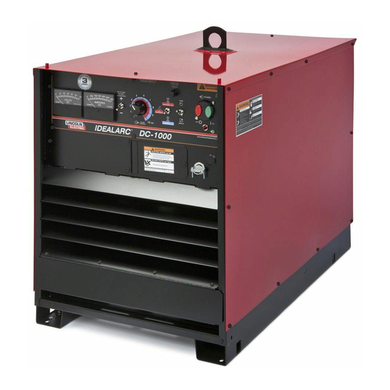
IDEALARC
DC-1000
®
For use with machines having Code Numbers:
9919, 9920, 9921, 9922, 9923, 9924, 9925, 10293, 11305, 11330, 11331,
11332, 11333, 11334, 11681, 11682, 11683, 11684, 11950, 11951, 11952,
11953
SERVICE MANUAL
SVM123-B
| Issue D ate 12, Jul
© Lincoln Global, Inc. All Rights Reserved.
NOTE: This manual will cover most of the troubleshooting and repair
procedures for the code numbers listed. Some variances may exist when
troubleshooting/repairing later code numbers.
Advertisement
Chapters
Table of Contents
Troubleshooting

Subscribe to Our Youtube Channel
Related Manuals for Lincoln Electric IDEALARC DC-1000


Summary of Contents for Lincoln Electric IDEALARC DC-1000
- Page 1 NOTE: This manual will cover most of the troubleshooting and repair procedures for the code numbers listed. Some variances may exist when troubleshooting/repairing later code numbers. IDEALARC DC-1000 ® For use with machines having Code Numbers: 9919, 9920, 9921, 9922, 9923, 9924, 9925, 10293, 11305, 11330, 11331, 11332, 11333, 11334, 11681, 11682, 11683, 11684, 11950, 11951, 11952, 11953 SERVICE MANUAL...
- Page 2 Miami, Florida 33135 or CSA Standard W117.2-1974. A Free copy of “Arc Welding Safety” booklet E205 is available from the Lincoln Electric Company, 22801 St. Clair Avenue, Cleveland, Ohio 44117-1199. BE SURE THAT ALL INSTALLATION, OPERATION, MAINTENANCE AND REPAIR PROCEDURES ARE PERFORMED ONLY BY QUALIFIED INDIVIDUALS.
- Page 3 SAFETY ELECTRIC SHOCK can kill. ARC RAYS can burn. 3.a. The electrode and work (or ground) circuits 4.a. Use a shield with the proper filter and cover are electrically “hot” when the welder is on. plates to protect your eyes from sparks and Do not touch these “hot”...
- Page 4 SAFETY WELDING and CUTTING CYLINDER may explode SPARKS can cause fire or if damaged. explosion. 7.a. Use only compressed cylinders containing the correct shielding gas for the 6.a. Remove fire hazards from the welding area.If process used and properly operating this is not possible, cover them to prevent the welding sparks regulators designed for the gas and from starting a fire.
- Page 5 SAFETY 6. Eloigner les matériaux inflammables ou les recouvrir afin de PRÉCAUTIONS DE SÛRETÉ prévenir tout risque dʼincendie dû aux étincelles. Pour votre propre protection lire et observer toutes les instructions 7. Quand on ne soude pas, poser la pince à une endroit isolé de et les précautions de sûreté...
- Page 6 2004/108/EC. It was manufactured in conformity with a national standard that implements a harmonized standard: EN 60974-10 Electromagnetic Compatibility (EMC) Product Standard for Arc Welding Equipment. It is for use with other Lincoln Electric equipment. It is designed for industrial and professional use. Introduction All electrical equipment generates small amounts of electromagnetic emission.
- Page 7 SAFETY Electromagnetic Compatibility (EMC) The size of the surrounding area to be considered will depend on the structure of the building and other activities that are taking place. The surrounding area may extend beyond the boundaries of the premises. Methods of Reducing Emissions Mains Supply Welding equipment should be connected to the mains supply according to the manufacturer’s recommenda- tions.
- Page 8 - MASTER TABLE OF CONTENTS FOR ALL SECTIONS - Page Safety ................i-vi Installation .
- Page 9 TABLE OF CONTENTS - INSTALLATION SECTION Installation ................A-1 Technical Specifications .
- Page 10 INSTALLATION TECHNICAL SPECIFICATIONS – DC-1000 INPUT - THREE PHASE ONLY Input Current at Rated Output Standard Voltage 100% Duty Cycle 60% Duty Cycle 50% Duty Cycle 230/460/60 193/96.5 215/108 230/115 575/60 77.2 220/380/440/50/60 230/133/115 193/112/96.5 215/124/108 380/500/50/60 112/85 124/94 133/101 415/50/60 RATED OUTPUT Duty Cycle...
- Page 11 INSTALLATION A permanent lifting eye is located at the top of the SAFETY PRECAUTIONS machine and is positioned so that it acts as nearly as Read this entire installation section before you possible through the center of gravity. This lift eye fits start installation.
- Page 12 INSTALLATION RECONNECT PROCEDURE To reconnect a multiple voltage machine to a different voltage, remove input power and change the position of the reconnect board on the Reconnect Panel. Multiple voltage machines are shipped connected to Follow The Input Connection Diagram located on the the highest input voltage listed on the machineʼs rating inside of Case Back Input Access Door.
- Page 13 INSTALLATION FIGURE A.2 INPUT SUPPLY CONNECTION DIAGRAM WARNING: ALL INPUT POWER MUST BE ELECTRICALLY DISCONNECTED BEFORE TOUCHING PANEL. NOTE: MACHINES ARE SHIPPED FROM FACTORY CONNECTED FOR HIGHEST VOLTAGE. CONNECTION FOR 440 VOLTS 50 Hz. (460v 60Hz.) TAPE ON RECONNECT PANEL, LOOSEN ALL HEX BOLTS, PULL MOVABLE LINKS, AND ROTATE LINKS TO THEIR NEW POSITIONS.
- Page 14 INSTALLATION OUTPUT CONNECTIONS Control Cable Connection Terminal strips with screw connections are located Output Studs behind the hinged door on the front of the power The output leads are connected to the output termi- source to make all the control cable connections for nals.
-
Page 15: Table Of Contents
TABLE OF CONTENTS - OPERATION SECTION Operation ................B-1 Operating Instructions . -
Page 16: Operation
OPERATION OPERATING INSTRUCTIONS NOTE: All P.C. boards are protected by a moisture resistant coating. When the welder is operated, this coating will “bake off” of certain power WARNING resistors that normally operate at high temper- atures emitting some smoke and odor for a ELECTRIC SHOCK can kill. -
Page 17: Set-Up For Various Procedures
OPERATION 2. NA-3 - The NA-3 should be set for the mode being Remote Output Control - (Optional) used on the power source. If using either of the CV The K775 Remote Output Control consists of a control modes, the NA-3 CC board switch should be set for box with 28 ft. -
Page 18: Connections For Semi-Automatic Or Automatic Wire Feeder Control
OPERATION 3. NA-5 - Set the DC-1000 mode switch to the NOTE: The IDEALARC ® DC-1000 Auxiliary Power process being used - CV(I) Innershield or CV(S) Circuit (at #31 and #32 on the terminal strip) Sub Arc. Set the DC-1000 machine/remote switch supplies 115-volt AC power to the wire feeding in the remote position. -
Page 19: Connecting The Na-5 To The Idealarc Dc-1000
ACCESSORIES 5. Extend wire feeder control cable lead #21 so it can CAUTION be connected directly to the work piece. The IDEALARC ® DC-1000 must be properly grounded. a. Make a bolted connection using AWG #14 or larger insulated wire. ____________________________________________________ b. -
Page 20: Connecting The Ln-8 To The Idealarc Dc-1000
ACCESSORIES NOTE: The connection diagram shown in Figure B.2 shows the electrode connected for positive polarity. To change polarity: a. Set the IDEALARC DC-1000 ON/OFF PUSH ® BUTTON to OFF. b. Move the electrode cable to the Negative (-) output terminal. c. -
Page 21: Connecting The Ln-9 Wire Feeder To The Idealarc Dc-1000
ACCESSORIES CONNECTING THE LN-9 WIRE FEEDER TO THE IDEALARC ® DC-1000 1. Set the ON/OFF PUSH BUTTON to the OFF posi- tion. 2. Disconnect AC input power to the IDEALARC ® 1000. 3. Connect the wire feeder control cable leads to the DC-1000 terminal strip. -
Page 22: Connecting The Ln-7 Wire Feeder To The Idealarc Dc-1000
ACCESSORIES CONNECTING THE LN-7 WIRE FEEDER TO THE IDEALARC ® DC-1000 1. Set the IDEALARC DC-1000 ON/OFF PUSH BUT- ® TON to OFF. 2. Disconnect main AC input power to the IDEALARC ® DC-1000. 3. Connect the wire feeder control cable leads to the IDEALARC DC-1000 terminal strip as shown in ®... - Page 23 TABLE OF CONTENTS - ACCESSORIES SECTION Accessories ................C-1 Options/Accessories .
- Page 24 ACCESSORIES OPTIONS / ACCESSORIES • Remote Control Box Assembly (K775) • LN-7 • LN-8 Semi-Automatic Wire Feeders • LN-9 • NA-3 Automatic Wire Feeders • NA-5 • LT-7 and LT-56 Tractors METERS Optional factory-installed voltmeter and ammeter are available. REMOTE OUTPUT CONTROL - (OPTIONAL) The K775 Remote Output Control consists of a control box with 28 ft.
- Page 25 TABLE OF CONTENTS - MAINTENANCE SECTION Maintenance ................D-1 Safety Precautions .
- Page 26 MAINTENANCE SAFETY PRECAUTIONS The control board is designed with adequate protection so that no damage will occur if the remote control leads are shorted together or are grounded to the case. The WARNING machine will automatically shut down if such faults do occur.
- Page 27 MAINTENANCE FIGURE D.1 - Major Component Locations 1. Case Front & Control Box 2. Case Back Assembly 3. Base, Fan, Roof and Case Sides 4. Output Rectifier & Choke Assembly 5. Lift Bale & Transformer Assembly 6. S78 Contactor IDEALARC ®...
- Page 28 NOTES IDEALARC ® DC-1000...
- Page 29 TABLE OF CONTENTS-THEORY OF OPERATION SECTION Theory of Operation ..............E-1 General Description .
- Page 30 THEORY OF OPERATION FIGURE E.2 - INPUT LINE VOLTAGE, CONTACTOR, AND MAIN TRANSFORMER GENERAL DESCRIPTION INPUT LINE VOLTAGE, CONTACTOR, AND MAIN TRANSFORMER The DC 1000 is an SCR - controlled DC power source. It is designed to be controlled with a single range The desired three phase power is connected to the potentiometer output control.
- Page 31 THEORY OF OPERATION FIGURE E.3 - OUTPUT, RECTIFICATION, CONTROL AND FEEDBACK OUTPUT RECTIFICATION, CONTROL AND FEEDBACK The neutrals of the Main Transformer secondary wind- The Pilot Relay signals the Firing Board circuit to sup- ings are connected together and the six starts are con- ply gate pulses to the SCR Bridge.
- Page 32 THEORY OF OPERATION FIGURE E.4 - PROTECTION DEVICES AND CIRCUITS (CONTACTOR HOLD-IN) PROTECTION DEVICES AND CIRCUITS (CONTACTOR HOLD-IN) Two thermostats protect the DC-1000 from excessive The Remote Control circuit is also protected from operating temperatures. Excessive operating tempera- “grounds” or voltage intrusions. If the #73, #74, #75, tures may be caused by a lack of cooling air or operat- #76 or #77 leads come in contact with either of the ing the machine beyond the duty cycle and output rat-...
- Page 33 THEORY OF OPERATION FIGURE E.5 - SCR OPERATION SCR OPERATION A silicon controlled rectifier (SCR) is a three terminal An SCR is fired by a short burst of current into the gate. device used to control rather large currents to a load. This gate pulse must be more positive than the cath- An SCR acts very much like a switch.
- Page 34 NOTES IDEALARC ® DC-1000...
- Page 35 TABLE OF CONTENTS - TROUBLESHOOTING AND REPAIR Troubleshooting and Repair ............. .F-1 How to Use Troubleshooting Guide .
-
Page 36: How To Use Troubleshooting Guide
HOW TO USE TROUBLESHOOTING GUIDE WARNING Service and Repair should only be performed by Lincoln Electric Factory Trained Personnel. Unauthorized repairs performed on this equipment may result in danger to the technician and machine operator and will invalidate your factory warranty. For your safety and to avoid Electrical Shock, please observe all safety notes and precautions detailed throughout this manual. -
Page 37: Pc Board Troubleshooting Procedures
Do not touch electrically hot parts. - If you return a PC board to The Lincoln Electric Company for credit, it must be in the static-shielding bag. This will prevent further damage and allow prop- CAUTION er failure analysis. - Page 38 - Replace. CAUTION If for any reason you do not understand the test procedures or are unable to perform the tests/repairs safely, contact the Lincoln Electric Service Department for technical troubleshooting assistance before you proceed. Call 1-888-935-3877. IDEALARC ®...
- Page 39 DC-1000. CAUTION If for any reason you do not understand the test procedures or are unable to perform the tests/repairs safely, contact the Lincoln Electric Service Department for technical troubleshooting assistance before you proceed. Call 1-888-935-3877. IDEALARC ®...
- Page 40 7. Perform Active SCR Test. CAUTION If for any reason you do not understand the test procedures or are unable to perform the tests/repairs safely, contact the Lincoln Electric Service Department for technical troubleshooting assistance before you proceed. Call 1-888-935-3877. IDEALARC ®...
- Page 41 CAUTION If for any reason you do not understand the test procedures or are unable to perform the tests/repairs safely, contact the Lincoln Electric Service Department for technical troubleshooting assistance before you proceed. Call 1-888-935-3877. IDEALARC ®...
- Page 42 6. Perform Active SCR Test. CAUTION If for any reason you do not understand the test procedures or are unable to perform the tests/repairs safely, contact the Lincoln Electric Service Department for technical troubleshooting assistance before you proceed. Call 1-888-935-3877. IDEALARC ®...
- Page 43 Check or replace. CAUTION If for any reason you do not understand the test procedures or are unable to perform the tests/repairs safely, contact the Lincoln Electric Service Department for technical troubleshooting assistance before you proceed. Call 1-888-935-3877. IDEALARC ®...
- Page 44 “leaky”. Check or replace. See Wiring Diagram. CAUTION If for any reason you do not understand the test procedures or are unable to perform the tests/repairs safely, contact the Lincoln Electric Service Department for technical troubleshooting assistance before you proceed. Call 1-888-935-3877. IDEALARC ®...
- Page 45 - Replace. CAUTION If for any reason you do not understand the test procedures or are unable to perform the tests/repairs safely, contact the Lincoln Electric Service Department for technical troubleshooting assistance before you proceed. Call 1-888-935-3877. IDEALARC ®...
- Page 46 1000 amp output terminals. CAUTION If for any reason you do not understand the test procedures or are unable to perform the tests/repairs safely, contact the Lincoln Electric Service Department for technical troubleshooting assistance before you proceed. Call 1-888-935-3877. IDEALARC ®...
-
Page 47: Control Transformer (T2) Voltage Test
CONTROL TRANSFORMER (T2) VOLTAGE TEST WARNING Service and repair should be performed only by Lincoln Electric factory trained personnel. Unauthorized repairs performed on this equipment may result in danger to the technician or machine operator and will invalidate your factory warranty. For your safety and to avoid electrical shock, please observe all safety notes and precautions detailed throughout this manual. - Page 48 TROUBLESHOOTING AND REPAIR F-14 F-14 CONTROL TRANSFORMER (T2) VOLTAGE TEST (continued) FIGURE F.1 – CONTROL TRANSFORMER LEAD LOCATION CONTROL TRANSFORMER (T2) HARNESS PROCEDURE 1. Disconnect main AC input power to the machine. 2. Remove the Top and Case Sides. 3. Locate the Control Transformer (T2) on the left side of the Input Box (facing the back of the machine).
- Page 49 TROUBLESHOOTING AND REPAIR F-15 F-15 CONTROL TRANSFORMER (T2) VOLTAGE TEST (continued) FIGURE F.2 – CONTROL TRANSFORMER X1 AND X2 TEST POINTS 5. Locate Control Transformer leads X1 and X2 at in line connectors. See Figure F.2. 6. Apply power and test for 115 VAC between leads X1 to X2.
- Page 50 NOTES F-16 F-16 IDEALARC ® DC-1000...
-
Page 51: Main Transformer (T1) Voltage Test
MAIN TRANSFORMER (T1) VOLTAGE TEST WARNING Service and repair should be performed only by Lincoln Electric factory trained personnel. Unauthorized repairs performed on this equipment may result in danger to the technician or machine operator and will invalidate your factory warranty. For your safety and to avoid electrical shock, please observe all safety notes and precautions detailed throughout this manual. - Page 52 TROUBLESHOOTING AND REPAIR F-18 F-18 MAIN TRANSFORMER (T1) VOLTAGE TEST (continued) FIGURE F.3 – INPUT CONTACTOR, RECONNECT PANEL, AND PRIMARY LEADS TO MAIN TRANS- FORMER LOCATIONS PROCEDURE 1. Disconnect main AC input power to the 5. Test with an AC voltmeter for proper main AC machine.
- Page 53 TROUBLESHOOTING AND REPAIR F-19 F-19 MAIN TRANSFORMER (T1) VOLTAGE TEST (continued) FIGURE F.4 – MAIN SECONDARY LEAD TEST POINTS a. If one or more of the above voltage tests 9. Test with an AC voltmeter for 75 VAC for each are incorrect, check for loose or faulty phase angle winding as shown.
- Page 54 TROUBLESHOOTING AND REPAIR F-20 F-20 MAIN TRANSFORMER (T1) VOLTAGE TEST (continued) FIGURE F.5 – PHASE ANGLE WINDINGS TEST POINTS AND FIRING BOARD PIN LOCATION From Expected VAC Plug Lead Plug Lead #203 #204 75 VAC #205 #206 75 VAC #207 #208 75 VAC IDEALARC...
-
Page 55: Firing Board Test
FIRING BOARD TEST WARNING Service and repair should be performed only by Lincoln Electric factory trained personnel. Unauthorized repairs performed on this equipment may result in danger to the technician or machine operator and will invalidate your factory warranty. For your safety and to avoid electrical shock, please observe all safety notes and precautions detailed throughout this manual. - Page 56 TROUBLESHOOTING AND REPAIR F-22 F-22 FIRING BOARD TEST (continued) FIGURE F.6 – FIRING BOARD LED AND MOLEX PLUG LOCATIONS TEST PROCEDURE FOR NOR- WARNING MAL FIRING BOARD OPERA- JUMPERING LEADS 2 AND 4 ELECTRICALLY TION ENERGIZES MACHINEʼS OUTPUT TERMINALS. DO NOT TOUCH ELECTRICALLY HOT COMPO- 1.
- Page 57 TROUBLESHOOTING AND REPAIR F-23 F-23 FIRING BOARD TEST (continued) FIGURE F.7 – TERMINAL STRIP JUMPER WIRE CONNECTIONS 10. Rotate the output control potentiometer (R1). 12. If an LED continues to be lit and should not be, As the potentiometer is turned clockwise, the a circuit may be faulty on the Firing Board LEDs should glow brighter.
- Page 58 TROUBLESHOOTING AND REPAIR F-24 F-24 FIRING BOARD TEST (continued) FIGURE F.8 – OUTPUT PILOT RELAY 4CR LOCATION 15. Test the Output Pilot Relay (4CR) for operation by removing and replacing the jumper wire repeatedly from terminal #2. See Figure F.7. This should cause the relay contacts to open and close.
- Page 59 TROUBLESHOOTING AND REPAIR F-25 F-25 FIRING BOARD TEST (continued) TABLE F.1 – LED 7, 8 AND 9 CHECK LIST THEN LED 7 is ON AC power is being supplied to the Firing Board from leads #203 and #204 connected to the phase angle winding in the Main Transformer.
- Page 60 NOTES F-26 F-26 IDEALARC ® DC-1000...
-
Page 61: Control Board Test
CONTROL BOARD TEST WARNING Service and repair should be performed only by Lincoln Electric factory trained personnel. Unauthorized repairs performed on this equipment may result in danger to the technician or machine operator and will invalidate your factory warranty. For your safety and to avoid electrical shock, please observe all safety notes and precautions detailed throughout this manual. - Page 62 TROUBLESHOOTING AND REPAIR F-28 F-28 CONTROL BOARD TEST (continued) FIGURE F.9 – CONTROL BOARD LED AND PIN LOCATIONS TEST PROCEDURE FOR NORMAL CONTROL BOARD OPERATION 1. Remove main supply power to the DC-1000. 7. LED 4 should NOT be lit. LED 4 should light only if there is a “fault”...
- Page 63 TROUBLESHOOTING AND REPAIR F-29 F-29 CONTROL BOARD TEST (continued) FIGURE F.10 – LED 1 TEST POINTS POSSIBLE PROBLEMS PERTAINING TO THE CONTROL BOARD IF LED 1 does not light, when the start switch is 1. Check for 115 VAC at leads #255 to #256 plug c.
- Page 64 TROUBLESHOOTING AND REPAIR F-30 F-30 CONTROL BOARD TEST (continued) FIGURE F.11 – LED 2 OPEN CIRCUIT VOLTAGE TEST POINTS IF LED 2 does not light when #2 and #4 are 3. Test for continuity (zero ohms) from the nega- jumpered together. tive output terminal to lead #222 at plug J1 on the Control Board.
- Page 65 TROUBLESHOOTING AND REPAIR F-31 F-31 CONTROL BOARD TEST (continued) IF LED 3 does not light when the Start Button is IF LED 5 does not light and varies in brightness depressed (but LED 1 does light). when #2 and #4 are jumpered together, while the Output Control Potentiometer is rotated.
- Page 66 NOTES F-32 F-32 IDEALARC ® DC-1000...
-
Page 67: Static Scr Test
STATIC SCR TEST WARNING Service and repair should be performed only by Lincoln Electric factory trained personnel. Unauthorized repairs performed on this equipment may result in danger to the technician or machine operator and will invalidate your factory warranty. For your safety and to avoid electrical shock, please observe all safety notes and precautions detailed throughout this manual. - Page 68 TROUBLESHOOTING AND REPAIR F-34 F-34 STATIC SCR TEST (continued) FIGURE F.12 – FIRING AND CONTROL BOARD MOLEX PLUG LOCATIONS FIRING BOARD CONTROL BOARD PROCEDURE 1. Remove main supply power to the DC-1000. 2. Remove all Molex plugs from the firing board and control board.
- Page 69 TROUBLESHOOTING AND REPAIR F-35 F-35 STATIC SCR TEST (continued) FIGURE F.13 – SCR HEAT SIN ASSEMBLY TEST POINTS 3. Remove the red insulating paint from heat sink test points. See Figure F.13. NOTE: DO NOT DISASSEMBLE THE HEAT SINKS. 4. Using an analog ohmmeter, test the resistance from anode to cathode of SCR 1.
- Page 70 TROUBLESHOOTING AND REPAIR F-36 F-36 STATIC SCR TEST (continued) FIGURE F.14 – SNUBBER LOCATION AND CIRCUIT 5. Repeat Step 4 testing SCR 2, SCR 3, SCR 4, SCR 5, and SCR 6. To further check the SCRsʼ functions use an SCR tester and proceed to Active SCR Test.
-
Page 71: Active Scr Test
ACTIVE SCR TEST WARNING Service and repair should be performed only by Lincoln Electric factory trained personnel. Unauthorized repairs performed on this equipment may result in danger to the technician or machine operator and will invalidate your factory warranty. For your safety and to avoid electrical shock, please observe all safety notes and precautions detailed throughout this manual. - Page 72 TROUBLESHOOTING AND REPAIR F-38 F-38 ACTIVE SCR TEST (continued) FIGURE F.15 – FIRING BOARD AND CONTROL BOARD MOLEX LOCATIONS FIRING BOARD CONTROL BOARD PROCEDURE 1. Remove main supply power to the DC-1000. 2. Remove all Molex plugs from the Firing Board and Control Board.
- Page 73 TROUBLESHOOTING AND REPAIR F-39 F-39 ACTIVE SCR TEST (continued) FIGURE F.16 – HEAT SINK ASSEMBLY TEST POINTS 3. Remove the red insulating paint from heat sink test points. See Figure F.16. 4. Perform test procedure as follows. Refer to Figure F.17. Repeat test for all six SCRs. NOTE: Do not disassemble the heat sinks.
- Page 74 TROUBLESHOOTING AND REPAIR F-40 F-40 ACTIVE SCR TEST (continued) FIGURE F.17 – SILICON CONTROLLED RECTIFIER (SCR) TEST SETUP 5. To test SCRs, construct the circuit outlined in 6. With switch SW1 closed, close switch SW2 for Figure F.17. Use one 6V lantern battery. two seconds and release.
- Page 75 TROUBLESHOOTING AND REPAIR F-41 F-41 NORMAL OPEN CIRCUIT VOLTAGE WAVEFORM CONSTANT CURRENT MODE – NO LOAD This is the typical DC open circuit volt- age waveform generated from a prop- erly operating machine. Note that each vertical division represents 50 volts and that each horizontal division rep- resents 2 milliseconds in time.
- Page 76 TROUBLESHOOTING AND REPAIR F-42 F-42 NORMAL OPEN CIRCUIT VOLTAGE WAVEFORM CONSTANT VOLTAGE INNERSHIELD - MAXIMUM OUTPUT SETTINGS – NO LOAD This is the typical DC open circuit volt- age waveform generated from a prop- erly operating machine. Note that each vertical division represents 50 volts and that each horizontal division rep- resents 2 milliseconds in time.
- Page 77 TROUBLESHOOTING AND REPAIR F-43 F-43 NORMAL OPEN CIRCUIT VOLTAGE WAVEFORM CONSTANT VOLTAGE INNERSHIELD MINIMUM OUTPUT SETTING – NO LOAD This is the typical DC open circuit volt- age waveform generated from a prop- erly operating machine. Note that each vertical division represents 50 volts and that each horizontal division rep- resents 2 milliseconds in time.
- Page 78 TROUBLESHOOTING AND REPAIR F-44 F-44 TYPICAL OUTPUT VOLTAGE WAVEFORM - MACHINE LOADED CONSTANT VOLTAGE INNERSHIELD MODE This is the typical DC open circuit volt- age waveform generated from a prop- erly operating machine. Note that each vertical division represents 20 volts and that each horizontal division rep- resents 2 milliseconds in time.
- Page 79 TROUBLESHOOTING AND REPAIR F-45 F-45 TYPICAL OUTPUT VOLTAGE WAVEFORM - MACHINE LOADED - 500 AMP OUTPUT TERMINAL CONSTANT VOLTAGE INNERSHIELD MODE This is the typical DC open circuit volt- age waveform generated from a prop- erly operating machine. Note that each vertical division represents 20 volts and that each horizontal division rep- resents 2 milliseconds in time.
- Page 80 TROUBLESHOOTING AND REPAIR F-46 F-46 TYPICAL SCR GATE VOLTAGE WAVEFORM CONSTANT VOLTAGE INNERSHIELD MAXIMUM OUTPUT SETTING - NO LOAD This is the typical SCR gate pulse volt- age waveform. The machine was in an open circuit condition (no load) and operating properly.
- Page 81 TROUBLESHOOTING AND REPAIR F-47 F-47 ABNORMAL OPEN CIRCUIT VOLTAGE WAVEFORM CONSTANT VOLTAGE INNERSHIELD ONE OUTPUT SCR NOT FUNCTIONING MAXIMUM OUTPUT SETTING This is NOT the typical DC output volt- age waveform. One output SCR is not functioning. Note the “gap” in the waveform.
- Page 82 NOTES F-48 F-48 IDEALARC ® DC-1000...
- Page 83 INPUT CONTACTOR (1CR) CLEANING AND/OR REPLACEMENT WARNING Service and repair should be performed only by Lincoln Electric factory trained personnel. Unauthorized repairs performed on this equipment may result in danger to the technician or machine operator and will invalidate your factory warranty. For your safety and to avoid electrical shock, please observe all safety notes and precautions detailed throughout this manual.
- Page 84 TROUBLESHOOTING AND REPAIR F-50 F-50 INPUT CONTACTOR (1CR) CLEANING AND/OR REPLACEMENT (continued) FIGURE F.18 – INPUT CONTACTOR COVER REMOVAL FIGURE F.19 – INPUT CONTACTOR REMOVAL CLEANING PROCEDURE 1. Remove main input supply power to the DC-1000 and remove case top and sides. 2.
- Page 85 TROUBLESHOOTING AND REPAIR F-51 F-51 INPUT CONTACTOR (1CR) CLEANING AND/OR REPLACEMENT (continued) FIGURE F.20 – LEAD #257 AT SECONDARY THER- FIGURE F.21 – LEAD #211 AND #212 QUICK DIS- MOSTAT CONNECTS CONTACTOR REPLACEMENT WARNING Removal DO NOT APPLY INPUT POWER 1.
- Page 86 TROUBLESHOOTING AND REPAIR F-52 F-52 INPUT CONTACTOR (1CR) CLEANING AND/OR REPLACEMENT (continued) INSTALLATION 1. Install input contactor using a 7/16” socket wrench. Attach the four mounting bolts, nuts, and associated washers (or tighten the two bot- tom bolts and nuts, and attach the top two). 2.
- Page 87 SCR OUTPUT BRIDGE REPLACEMENT WARNING Service and repair should be performed only by Lincoln Electric factory trained personnel. Unauthorized repairs performed on this equipment may result in danger to the technician or machine operator and will invalidate your factory warranty. For your safety and to avoid electrical shock, please observe all safety notes and precautions detailed throughout this manual.
- Page 88 TROUBLESHOOTING AND REPAIR F-54 F-54 SCR OUTPUT BRIDGE REPLACEMENT (continued) FIGURE F.22 – PREPARATION FOR SCR OUTPUT BRIDGE REMOVAL PROCEDURE 1. Remove input power to machine. NOTE: It may be necessary to move or remove the output choke to gain access to the bot- 2.
- Page 89 TROUBLESHOOTING AND REPAIR F-55 F-55 SCR OUTPUT BRIDGE REPLACEMENT (continued) FIGURE F.23 – SCR OUTPUT BRIDGE REMOVAL 10. Cut any necessary cable ties to allow for the WARNING SCR bridge assembly removal. 11. Using a 1/2” socket wrench, remove the four UPON REASSEMBLY, THE BRIDGE...
- Page 90 TROUBLESHOOTING AND REPAIR F-56 F-56 SCR OUTPUT BRIDGE REPLACEMENT (continued) FIGURE F.24 – INDIVIDUAL SCR ASSEMBLY HEAT SINK REMOVAL REMOVAL OF INDIVIDUAL SCR HEAT WARNING SINK ASSEMBLIES 1. Using a 9/16” wrench, remove two nuts, flat DO NOT DISASSEMBLE THE SCR FROM THE washers, and lock washers from the SCR HEAT SINK.
- Page 91 TROUBLESHOOTING AND REPAIR F-57 F-57 SCR OUTPUT BRIDGE REPLACEMENT (continued) SCR HEAT SINK INSTALLATION SCR OUTPUT BRIDGE INSTALLATION NOTE: Upon reassembly, apply a thin layer of NOTE: Upon reassembly, apply a thin layer of Lincoln E1868 (Dow Corning #340) heat Lincoln E1868 (Dow Corning #340) heat sink compound to all bolted electrical con- sink compound to all bolted electrical con-...
- Page 92 TROUBLESHOOTING AND REPAIR F-58 F-58 SCR OUTPUT BRIDGE REPLACEMENT (continued) 7. Using a 3/8” socket wrench, attach the two 10. Using a 9/16” socket and open-end wrench, screws (one on each side) holding the SCR attach the two bolts and nuts holding the shunt assembly rails to the front panel assembly.
- Page 93 REMOVAL AND REASSEMBLY OF LIFT BALE WARNING Service and repair should be performed only by Lincoln Electric factory trained personnel. Unauthorized repairs performed on this equipment may result in danger to the technician or machine operator and will invalidate your factory warranty. For your safety and to avoid electrical shock, please observe all safety notes and precautions detailed throughout this manual.
- Page 94 TROUBLESHOOTING AND REPAIR F-60 F-60 REMOVAL AND REASSEMBLY OF LIFT BALE (continued) FIGURE F.25 – LIFT BAIL REMOVAL REMOVAL PROCEDURE 1. Remove input power to machine. 6. Using a 9/16” socket wrench, remove the four bolts and associated washers mounting the lift 2.
- Page 95 TROUBLESHOOTING AND REPAIR F-61 F-61 REMOVAL AND REASSEMBLY OF LIFT BALE (continued) REASSEMBLY PROCEDURE 1. Place the lift bail onto the IDEALARC ® DC-1000 4. Using a 3/8” socket wrench, attach the two from the top, lowering straight onto the unit. screws holding the input contactor bracket to the lift bail.
- Page 96 NOTES F-62 F-62 IDEALARC ® DC-1000...
- Page 97 MAIN TRANSFORMER REMOVAL AND INSTALLATION WARNING Service and repair should be performed only by Lincoln Electric factory trained personnel. Unauthorized repairs performed on this equipment may result in danger to the technician or machine operator and will invalidate your factory warranty. For your safety and to avoid electrical shock, please observe all safety notes and precautions detailed throughout this manual.
- Page 98 TROUBLESHOOTING AND REPAIR F-64 F-64 MAIN TRANSFORMER REMOVAL AND INSTALLATION (continued) FIGURE F.26 – MAIN TRANSFORMER DISASSEMBLY IDEALARC ® DC-1000...
- Page 99 TROUBLESHOOTING AND REPAIR F-65 F-65 MAIN TRANSFORMER REMOVAL AND INSTALLATION (continued) MAIN TRANSFORMER DISASSEMBLY COIL REMOVAL AND REPLACEMENT 1. Perform Removal and Reassembly of Lift 1. Label and disconnect leads to the coils that are Bale Procedure. being removed or replaced (see Wiring Diagram).
- Page 100 TROUBLESHOOTING AND REPAIR F-66 F-66 MAIN TRANSFORMER REMOVAL AND INSTALLATION (continued) TRANSFORMER REASSEMBLY 1. Using a hoist, carefully lift the top iron onto the 5. With leads still attached, carefully reposition the assembly. Lightly tap on the top of the iron. input contactor bracket onto the case back assembly.
- Page 101 TROUBLESHOOTING AND REPAIR F-67 F-67 RETEST AFTER REPAIR Testing is required after the removal of any mechanical part that could affect the machineʼs elec- trical characteristics, or if any electrical components are repaired or replaced. INPUT IDLE AMPS AND WATTS Input Volts/Phase/Hertz Maximum Idle Amps Maximum Idle KW...
- Page 102 NOTES F-68 F-68 IDEALARC ® DC-1000...
- Page 103 TABLE OF CONTENTS - DIAGRAM SECTION Electrical Diagrams ..............G-1 Wiring Diagram - Codes 9922, 9924, 9925, 10293M, 11333 (L9008) .
- Page 104 ELECTriCaL DiaGrams WiriNG DiaGram - CODEs 9922, 9924, 9925, 10293m, 11333 (L9008) OUTPUT CONTROL TO GROUND PER CENTER TERMINAL ON FUSE HOLDER NATIONAL ELECTRICAL METER KIT CODE (OPTIONAL) N.C. START STOP 3 PHASE POWER PRIMARY SUPPLY COILS 76 77 SINGLE OR DUAL VOLTAGE INPUT PANEL N.D.
- Page 105 ELECTriCaL DiaGrams WiriNG DiaGram - aLL OThEr CODEs (L9008-1) OUTPUT CONTROL TO GROUND PER CENTER TERMINAL ON FUSE HOLDER NATIONAL ELECTRICAL METER KIT CODE (OPTIONAL) N.C. STOP START 3 PHASE POWER PRIMARY SUPPLY COILS 76 77 SINGLE OR DUAL VOLTAGE INPUT PANEL T.S.2 T.S.3 SHOWN CONNECTED FOR LOW VOLTAGE...
-
Page 106: Electrical Diagrams
ELECTriCaL DiaGrams sChEmaTiC - COmpLETE maChiNE - CODEs 9922, 9924, 9925, 10293m, 11333 (G2147) CHANGE DETAIL: REVISED GRAPHICS ENGINEERING CONTROLLED MANUFACTURER: START STOP 120VAC SECONDARY PRIMARY TO GROUND "-" OUTPUT STUD FAN MOTOR 120VAC 500 AMP OUTPUT TS 2 OUTPUT SNUBBER SCR1 SCR3... -
Page 107: Schematic - Complete Machine - All Other Codes (G2147-1
ELECTriCaL DiaGrams sChEmaTiC - COmpLETE maChiNE - aLL OThEr CODEs (G2147-1) ENGINEERING CONTROLLED CHANGE DETAIL: NEW. MANUFACTURER: TOP FRONT RIGHT START STOP TOP FRONT RIGHT 120VAC 257A CHOKE SECONDARY ON SECONDARY LEAD CHOKE LEAD LEFT SIDE CONTROL BOX AREA LOCATED TOP RIGHT REAR TO GROUND (NEAR INPUT CONTACTOR) REAR... -
Page 108: Schematic Control Pc Board (L8556)
ELECTriCaL DiaGrams sChEmaTiC CONTrOL pC bOarD (L8556) ENGINEERING CONTROLLED CHANGE DETAIL: REVISED SCR1 AMPS MANUFACTURER: 12 A THIS DOCUMENT CONTAINS PROPRIETARY INFORMATION OWNED BY LINCOLN GLOBAL, INC. AND MAY NOT BE DUPLICATED, COMMUNICATED PROPRIETARY & CONFIDENTIAL: TO OTHER PARTIES OR USED FOR ANY PURPOSE WITHOUT THE EXPRESS WRITTEN PERMISSION OF LINCOLN GLOBAL, INC. MANUFACTURING TOLERANCE PER E2056 SCALE: CONTROL:... -
Page 109: Schematic - Firing Pc Board (L8337
ELECTriCaL DiaGrams sChEmaTiC - firiNG pC bOarD L8337) NOTE: This diagram is for reference only. It may not be accurate for all machines covered by this manual. iDEaLarC ® DC-1000... -
Page 110: Schematic - Output Snubber Pc Board (S19699
ELECTriCaL DiaGrams sChEmaTiC - OuTpuT sNubbEr pC bOarD (s19699) 320V 600V 160J WELDER OUTPUT TO FRAME STUDS 320V 600V 160J CAPICITORS MFD/VOLTS A.N.S.I. ELECTRICAL SYMBOLS PER E1537 DC-1000 SINCE COMPONENTS OR CIRCUITRY ON A PRINTED CIRCUIT BOARD MAY CHANGE OUTPUT SNUBBER SCHEMATIC WITHOUT AFFECTING THE INTERCHANGEABILITY OF A COMPLETE BOARD, THIS 19699 DIAGRAM, MAY NOT SHOW THE EXACT COMPONENTS OR CIRCUITRY OF CONTROLS...
Need help?
Do you have a question about the IDEALARC DC-1000 and is the answer not in the manual?
Questions and answers