Table of Contents
Advertisement
Quick Links
Operator's Manual
IDEALARC
Register your machine:
www.lincolnelectric.com/register
Authorized Service and Distributor Locator:
www.lincolnelectric.com/locator
Save for future reference
Date Purchased
Code:
(ex: 10859)
Serial:
(ex: U1060512345)
IM602-A
| Issue D ate 11-Aug
© Lincoln Global, Inc. All Rights Reserved.
DC655
®
For use with machines having Code Numbers:
10501; 10502; 10503; 10504; 10506;
10507; 10508; 10509; 10510; 11324
Advertisement
Table of Contents

Subscribe to Our Youtube Channel
Related Manuals for Lincoln Electric 10501


Summary of Contents for Lincoln Electric 10501
- Page 1 Operator’s Manual IDEALARC DC655 ® For use with machines having Code Numbers: 10501; 10502; 10503; 10504; 10506; 10507; 10508; 10509; 10510; 11324 Register your machine: www.lincolnelectric.com/register Authorized Service and Distributor Locator: www.lincolnelectric.com/locator Save for future reference Date Purchased Code: (ex: 10859)
- Page 2 351040, Miami, Florida 33135 or CSA Standard W117.2-1974. A Free copy of “Arc Welding Safety” booklet E205 is available from the Lincoln Electric Company, 22801 St. Clair Avenue, Cleveland, Ohio 44117-1199. BE SURE THAT ALL INSTALLATION, OPERATION, MAINTENANCE AND REPAIR PROCEDURES ARE PERFORMED ONLY BY QUALIFIED INDIVIDUALS.
- Page 3 SAFETY ARC RAYS can burn. ELECTRIC SHOCK can 4.a. Use a shield with the proper filter and cover kill. plates to protect your eyes from sparks and 3.a. The electrode and work (or ground) circuits the rays of the arc when welding or observing are electrically “hot”...
- Page 4 SAFETY WELDING and CUTTING CYLINDER may explode SPARKS can if damaged. cause fire or explosion. 7.a. Use only compressed gas cylinders 6.a. Remove fire hazards from the welding area. containing the correct shielding gas for the If this is not possible, cover them to prevent process used and properly operating the welding sparks from starting a fire.
- Page 5 SAFETY 5. Toujours porter des lunettes de sécurité dans la zone de PRÉCAUTIONS DE SÛRETÉ soudage. Utiliser des lunettes avec écrans lateraux dans les zones où lʼon pique le laitier. Pour votre propre protection lire et observer toutes les instruc- tions et les précautions de sûreté...
- Page 6 2004/108/EC. It was manufactured in conformity with a national standard that implements a harmonized standard: EN 60974-10 Electromagnetic Compatibility (EMC) Product Standard for Arc Welding Equipment. It is for use with other Lincoln Electric equipment. It is designed for industrial and professional use. Introduction All electrical equipment generates small amounts of electromagnetic emission.
- Page 7 SAFETY Electromagnetic Compatibility (EMC) The size of the surrounding area to be considered will depend on the structure of the building and other activities that are taking place. The surrounding area may extend beyond the boundaries of the premises. Methods of Reducing Emissions Public Supply System Welding equipment should be connected to the public supply system according to the manufacturer’s rec- ommendations.
- Page 8 Electric for advice or information about their use of our products. We respond to our customers based on the best information in our posses- sion at that time. Lincoln Electric is not in a position to warrant or guarantee such advice, and assumes no liability, with respect to such infor- mation or advice.
-
Page 9: Table Of Contents
viii viii TABLE OF CONTENTS PAGE INSTALLATION ..............SECTION A Technical Specifications . -
Page 10: Installation
TECHNICAL SPECIFICATIONS – DC-655 INPUT - THREE PHASE ONLY Input Current at Rated Output Standard Code 100% Duty Cycle 60% Duty Cycle Volatge Number 122/61 150/75 230/460/60 10501 122/61/49 150/75/60 230/460/575/60 10502, 11324 135/67.5 166/83 208/416/60 10503 460/60 10504 575/60... -
Page 11: Graphic Symbols That Appear On Rating Plate
INSTALLATION GRAPHIC SYMBOLS THAT APPEAR ON RATING PLATE (LOCATED ON CASE BACK) Constant Voltage Output 3 Phase transformer with Characteristics rectified DC output INPUT POWER GMAW FCAW THREE PHASE Designates welder complies with Designates welder can be used National Electrical Manufacturers in environments with increased Association requirements EW 1 NEMA EW 1 (100%) -
Page 12: Safety Precautions
INSTALLATION Read entire installation section before starting INPUT installation. CONTACTOR (CR1) SAFETY PRECAUTIONS INPUT POWER SUPPLY WARNING CABLE WITH BUSHING RECONNECT OR BOX CONNECTOR PANEL ASSEMBL Y ELECTRIC SHOCK can kill. • Only qualified personnel should perform this installation. • Turn the input power OFF at the discon- nect switch or fuse box before working on this equipment. -
Page 13: Input Power Supply Connections
I N S T A L L A N D T I G H T E N A L L O F T H E H E X N U T S . TRANSF. D - U F LINKS M18225 THE LINCOLN ELECTRIC CO., CLEVELAND OHIO U.S.A. FIGURE A.2 Dual Voltage Machine Reconnection Procedure DC-655... -
Page 14: Output Connections
INSTALLATION OUTPUT CONNECTIONS 2. Connect the electrode cable to the positive terminal marked “+”. ELECTRODE AND WORK CABLES 3. Remove the terminal strip access cover panel on the lower case front. Refer to figure A.3 for the Use the shortest possible cable lengths. See Table location. -
Page 15: Auxiliary Power And Control Connections
INSTALLATION AUXILIARY POWER AND 14 PIN MS TYPE RECEPTACLE (For MS3106A-20-27PX Plug. L.E.C. Part #S12020-32) CONTROL CONNECTIONS Refer to the figure A.4 for the available circuits in the Located at the lower front of the welder behind a 14 pin receptacle. hinged door is a 115VAC duplex receptacle for auxil- iary power (Domestic and Canadian Models only) and 42 VAC is available at receptacle pins I and K. -
Page 16: Terminal Strips
INSTALLATION TERMINAL STRIPS Terminal strips are available behind the cover panel on the lower case front to connect wire feeder control cables that do not have a 14 Pin MS-type connector. Refer to figure A.3 for the location of this cover panel. These terminals supply the connections as shown in the following Terminal Strip charts. -
Page 17: Operation
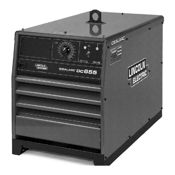
OPERATION SAFETY PRECAUTIONS GENERAL DESCRIPTION Read and understand this entire section before oper- The DC-655 is an energy efficient constant voltage DC power ating the machine. source that produces outstanding arc characteristics for multi- ple CV or CC welding processes GENERAL WARNINGS Four models are available: Domestic - all 60 Hertz models except 230/460/575v. -
Page 18: Design Features And Advantages
OPERATION DESIGN FEATURES AND ADVANTAGES • Optional dual feeder kit for like polarity connection of • Separate output terminals for selecting high or low two wire feeders. Easy panel installation. inductance as recommended for the welding process. • Optional Dual Process Switch for two processes with polarity change and electrical isolation. -
Page 19: Controls And Settings
OPERATION CONTROLS AND SETTINGS All operator controls and adjustments are located on the case front of the DC-655. Refer to Figures B.1, and B.2 and corresponding explanations. DC-655 FIGURE B.1 CONTROL PANEL CONTROLS 1. INPUT POWER ON/OFF SWITCH - This tog- remote device such as a wire feeder closes the #2 gle switch turns the machine on or off. - Page 20 OPERATION This mode is used for stick welding (SMAW) and 7. ARC FORCE CONTROL - This control is only func- CC air carbon-arc gouging, and employs a “Hot tional in CC Stick mode. It prevents “stubbing” of Start” feature and an Arc Force Control. CC the electrode by providing the extra weld current mode may also be used for CC submerged arc that linearly increases as the welding voltage...
-
Page 21: Auxiliary Power
OPERATION 3. 42VAC 10 AMP CIRCUIT BREAKER - This DC-655 machines can also supply 115 volt AC auxil- breaker protects the 42VAC auxiliary circuits locat- iary power through the wire feeder receptacle. A 20 ed in the terminal strip and MS-receptacle. amp circuit breaker on the Domestic and Canadian models, except for a 15 amp on Canadian Code 4. -
Page 22: Welding Performance
OPERATION SHORTED RECTIFIER FAULT THERMAL SHUTDOWN PROTECTION This welder has thermostatic protection from exces- sive duty cycles, overloads, loss of cooling, and high If a short occurs across one of the silicon controlled ambient temperature. When the welder is subjected to rectifiers of the DC-655, a potentially hazardous AC an overload or loss of cooling, a thermostat will open. - Page 23 OPERATION CV MODE CURRENT-LIMITING CV MIG and CV Sub-Arc modes employ electronic A general guideline for CC welding is to set Arc Force current limiting to limit excessive short circuit output to “Mid” position (#5) and increase (typically no more current which can result in undesirable arc character- than to #7) as necessary to prevent “stubbing”...
-
Page 24: Accessories
ACCESSORIES The DC-655 can be used to power any of NOTE: A dirty air filter may cause the thermal protec- tion of the DC-655 to prematurely activate. Remove the following Lincoln Wire feeders: and blow out, or wash and dry, the filter every two months, or less if in extremely dirty conditions. - Page 25 ACCESSORIES K1528-1 Dual Process Switch - (Cannot be used with K1486-1 Air Filter Kit) The Dual-Process Switch mounts easily to the front of the machine and is designed to provide a selection between left and right side output terminals. Each pair of output terminals can be switched to either the DC-655, high or low inductance terminals as desired.
-
Page 26: Maintenance
MAINTENANCE SAFETY PRECAUTIONS WARNING ELECTRIC SHOCK can kill. • Only qualified personnel should perform this maintenance. • Turn the input power OFF at the disconnect switch or fuse box before working on this equipment. • Do not touch electrically hot parts. -
Page 27: Troubleshooting
HOW TO USE TROUBLESHOOTING GUIDE WARNING Service and Repair should only be performed by Lincoln Electric Factory Trained Personnel. Unauthorized repairs performed on this equipment may result in danger to the technician and machine operator and will invalidate your factory warranty. For your safety and to avoid Electrical Shock, please observe all safety notes and precautions detailed throughout this manual. - Page 28 TROUBLESHOOTING Observe all Safety Guidelines detailed throughout this manual PROBLEMS POSSIBLE RECOMMENDED (SYMPTOMS) CAUSE COURSE OF ACTION PROBLEMS Input contactor (CR1) chatters. 1. Faulty input contactor (CR1). 2. Low line voltage. Machine input contactor does not If Power Pilot light is off: operate.
- Page 29 TROUBLESHOOTING Observe all Safety Guidelines detailed throughout this manual PROBLEMS POSSIBLE RECOMMENDED (SYMPTOMS) CAUSE COURSE OF ACTION PROBLEMS Machine has output, but no control. 1. Check the Local/Remote output switch (SW3) and associated leads. See wiring diagram. 2. Make sure the remote control leads #75, #76 and /or #77 are NOT grounded to either welding output.
- Page 30 TROUBLESHOOTING Observe all Safety Guidelines detailed throughout this manual PROBLEMS POSSIBLE RECOMMENDED (SYMPTOMS) CAUSE COURSE OF ACTION PROBLEMS Variable or sluggish welding arc. 1. Make sure the mode switch is in the proper position for the process. 2. Make sure the welding cables are sized correctly and the connec- tions are tight.
- Page 31 TROUBLESHOOTING Observe all Safety Guidelines detailed throughout this manual PROBLEMS POSSIBLE RECOMMENDED (SYMPTOMS) CAUSE COURSE OF ACTION PROBLEMS Machine will not weld. OCV is less 1. The machine may be in a over- than 1 volt. load condition. Refer to Machine Protection in the operation sec- tion.
- Page 32 TROUBLESHOOTING Observe all Safety Guidelines detailed throughout this manual PROBLEMS POSSIBLE RECOMMENDED (SYMPTOMS) CAUSE COURSE OF ACTION PROBLEMS Poor arc characteristics. 1. The negative welding cable may be connected to the wrong induc- tance tap. 2. Make sure the mode switch is in the proper position for the process.
-
Page 33: Diagrams
TROUBLESHOOTING Observe all Safety Guidelines detailed throughout this manual PROBLEMS POSSIBLE RECOMMENDED (SYMPTOMS) CAUSE COURSE OF ACTION PROBLEMS Thermal Protection Light comes ON 1. Check for obstructions that could and fan does not run. prevent the fan from turning. NOTE: Fan is thermal controlled and 2. - Page 34 TROUBLESHOOTING Observe all Safety Guidelines detailed throughout this manual PROBLEMS POSSIBLE RECOMMENDED (SYMPTOMS) CAUSE COURSE OF ACTION PROBLEMS Digital Ammeter not working properly 1. The meter PC board may not be or erratic display. receiving the auxiliary or sensing voltages. Check plug P3 and plugs P12 &...
- Page 35 TROUBLESHOOTING Observe all Safety Guidelines detailed throughout this manual PC BOARD TROUBLESHOOTING GUIDE - FIRING P.C. BOARD 1. All 10 LEDʼs must be ON when the POWER SOURCE is turned ON and the wire feederʼs trigger is closed, or a jumper is placed between 2 & 4, or the “OUTPUT TERMINALS SWITCH” is in the ON position. 2.
- Page 36 E-10 E-10 TROUBLESHOOTING Observe all Safety Guidelines detailed throughout this manual PC BOARD TROUBLESHOOTING GUIDE - THERMAL FAN/ SNUBBER P.C. BOARD NOTE: Fan will run for minimum of 5 minutes once fan turns on. 1. LED1 when ON indicates fan should be running. If ON and machine is cold, replace PCB. 2.
- Page 37 DIAGRAMS DC-655...
- Page 38 DIAGRAMS DC-655...
- Page 39 DIAGRAMS DC-655...
- Page 40 DIAGRAMS DC-655...
- Page 41 DIAGRAMS DC-655...
- Page 42 DIAGRAMS DC-655...
- Page 43 DIAGRAMS DC-655...
- Page 44 DIAGRAMS DC-655...
- Page 45 DIAGRAMS DC-655...
- Page 46 F-10 F-10 DIAGRAMS DC-655...
- Page 47 Keep your head out of fumes. Turn power off before servicing. Do not operate with panel open or Use ventilation or exhaust to guards off. WARNING remove fumes from breathing zone. Spanish Los humos fuera de la zona de res- Desconectar el cable de ali- No operar con panel abierto o AVISO DE...
- Page 48 Do not touch electrically live parts or Keep flammable materials away. Wear eye, ear and body protection. WARNING electrode with skin or wet clothing. Insulate yourself from work and ground. Spanish No toque las partes o los electrodos Mantenga el material combustible Protéjase los ojos, los oídos y el AVISO DE bajo carga con la piel o ropa moja-...
- Page 49 • World's Leader in Welding and Cutting Products • • Sales and Service through Subsidiaries and Distributors Worldwide • Cleveland, Ohio 44117-1199 U.S.A. TEL: 216.481.8100 FAX: 216.486.1751 WEB SITE: www.lincolnelectric.com...
Need help?
Do you have a question about the 10501 and is the answer not in the manual?
Questions and answers