Table of Contents
Advertisement
Quick Links
RETURN TO MAIN MENU
IM420-E
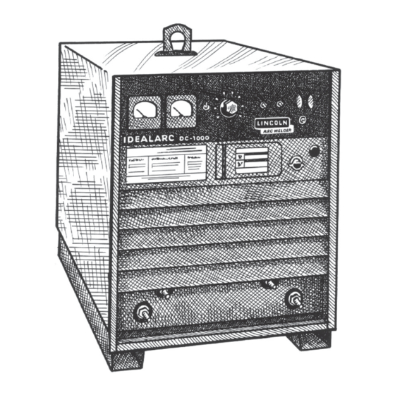
IDEALARC DC- 1 000
®
December, 2012
For use with machines having Code Numbers:
9919 - 9925, 10293, 11305, 11330, 11331, 11332, 11333, 11334,
11681 thru 11684, 11950 thru 11953
Safety Depends on You
Lincoln arc welding and cutting
equipment is designed and built
with safety in mind. However,
your overall safety can be
increased by proper installation
... and thoughtful operation on
your part. DO NOT INSTALL,
OPERATE OR REPAIR THIS
EQUIPMENT WITHOUT READ-
ING THIS MANUAL AND THE
SAFETY PRECAUTIONS CON-
TAINED THROUGHOUT. And,
most importantly, think before
you act and be careful.
OPERATOR'S MANUAL
Copyright © Lincoln Global Inc.
• World's Leader in Welding and Cutting Products •
• Sales and Service through Subsidiaries and Distributors Worldwide •
Cleveland, Ohio 44117-1199 U.S.A. TEL: 216.481.8100 FAX: 216.486.1751 WEB SITE: www.lincolnelectric.com
Advertisement
Table of Contents

Related Manuals for Lincoln Electric 9919


Summary of Contents for Lincoln Electric 9919
- Page 1 IDEALARC DC- 1 000 ® December, 2012 For use with machines having Code Numbers: 9919 - 9925, 10293, 11305, 11330, 11331, 11332, 11333, 11334, 11681 thru 11684, 11950 thru 11953 Safety Depends on You Lincoln arc welding and cutting equipment is designed and built with safety in mind.
- Page 2 351040, Miami, Florida 33135 or CSA Standard W117.2-1974. A Free copy of “Arc Welding Safety” booklet E205 is available from the Lincoln Electric Company, 22801 St. Clair Avenue, Cleveland, Ohio 44117-1199. BE SURE THAT ALL INSTALLATION, OPERATION, MAINTENANCE AND REPAIR PROCEDURES ARE PERFORMED ONLY BY QUALIFIED INDIVIDUALS.
- Page 3 SAFETY ARC RAYS can burn. ELECTRIC SHOCK can 4.a. Use a shield with the proper filter and cover kill. plates to protect your eyes from sparks and 3.a. The electrode and work (or ground) circuits the rays of the arc when welding or observing are electrically “hot”...
- Page 4 SAFETY WELDING and CUTTING CYLINDER may explode SPARKS can if damaged. cause fire or explosion. 7.a. Use only compressed gas cylinders 6.a. Remove fire hazards from the welding area. containing the correct shielding gas for the If this is not possible, cover them to prevent process used and properly operating the welding sparks from starting a fire.
- Page 5 SAFETY 5. Toujours porter des lunettes de sécurité dans la zone de PRÉCAUTIONS DE SÛRETÉ soudage. Utiliser des lunettes avec écrans lateraux dans les zones où l’on pique le laitier. Pour votre propre protection lire et observer toutes les instructions et les précautions de sûreté...
- Page 6 Electric for advice or information about their use of our products. We respond to our customers based on the best information in our posses- sion at that time. Lincoln Electric is not in a position to warrant or guarantee such advice, and assumes no liability, with respect to such infor- mation or advice.
-
Page 7: Table Of Contents
TABLE OF CONTENTS Page Installation........................Section A Technical Specifications .......................A-1 Safety Precautions.......................A-2 Location ........................A-2 Stacking ........................A-2 Input Wiring ........................A-2 Reconnect Procedures ..................A-3, A-4 Output Connections ......................A-5 _______________________________________________________________________________ Operation.........................Section B Safety Precautions .......................B-1 Product Description ......................B-1 To Set Polarity.......................B-2 Set-Up For Various Procedures..................B-2, B-3 ________________________________________________________________________________ Maintenance ....................Section D ....................D-1... -
Page 8: Installation
INSTALLATION TECHNICAL SPECIFICATIONS – DC-1000 INPUT - THREE PHASE ONLY Input Current at Rated Output Standard Voltage 50% Duty Cycle 100% Duty Cycle 60% Duty Cycle 230/460/60 193/96.5 215/108 230/115 575/60 77.2 220/380/440/50/60 193/112/96.5 215/124/108 230/133/115 380/500/50/60 112/85 124/94 133/101 415/50/60 RATED OUTPUT Duty Cycle... -
Page 9: Safety Precautions
INSTALLATION A permanent lifting eye is located at the top of the machine and SAFETY PRECAUTIONS is positioned so that it acts as nearly as possible through the Read this entire installation section before you center of gravity. This lift eye fits under the case of the second start installation. -
Page 10: Reconnect Procedures
INSTALLATION RECONNECT PROCEDURE To reconnect a multiple voltage machine to a different voltage, remove input power and change the position of the reconnect board on the Reconnect Panel. Multiple voltage machines are shipped connected to Follow The Input Connection Diagram located on the the highest input voltage listed on the machineʼs rating inside of Case Back Input Access Door. - Page 11 INSTALLATION FIGURE 2 FIGURE 3 IDEALARC® DC-1000...
-
Page 12: Output Connections
INSTALLATION OUTPUT CONNECTIONS Control Cable Connection Output Studs Terminal strips with screw connections are located behind the hinged door on the front of the power The output leads are connected to the output termi- source to make all the control cable connections for nals. -
Page 13: Operation
OPERATION OPERATING INSTRUCTIONS NOTE: All P.C. boards are protected by a moisture resistant coating. When the welder is operated, this coating will “bake off” of certain power resistors that WARNING normally operate at high temperatures emitting some ELECTRIC SHOCK can kill. smoke and odor for a short time. -
Page 14: Set-Up For Various Procedures
INSTALLATION Remote Output Control - (Optional) NOTE: Some processes and procedures may be bet- ter with the mode switch in the other CV position. If The K775 Remote Output Control consists of a control the mode switch position initially selected is not pro- box with 28 ft. - Page 15 INSTALLATION 3. NA-5 - Set the DC-1000 mode switch to the process being used - CV(I) Innershield or CV(S) Sub Arc. Set the DC-1000 machine/remote switch in the remote position. Set the OCV control four volts higher than the welding voltage and the inch speed at 1/2 the welding wire feed speed for the initial test weld.
-
Page 16: Maintenance
MAINTENANCE SAFETY PRECAUTIONS The control board is designed with adequate protec- tion so that no damage will occur if the remote control WARNING leads are shorted together or are grounded to the case. The machine will automatically shut down if such faults do occur. -
Page 17: Troubleshooting
HOW TO USE TROUBLESHOOTING GUIDE WARNING Service and Repair should only be performed by Lincoln Electric Factory Trained Personnel. Unauthorized repairs performed on this equipment may result in danger to the technician and machine operator and will invalidate your factory warranty. For your safety and to avoid Electrical Shock, please observe all safety notes and precautions detailed throughout this manual. - Page 18 TROUBLESHOOTING Observe all Safety Guidelines detailed throughout this manual PROBLEMS POSSIBLE RECOMMENDED (SYMPTOMS) CAUSE COURSE OF ACTION 1. Faulty input contactor (1CR). 1. Repair or replace. nput contactor (1CR) chatters. 2. Low line voltage. 2. Check input power. 3. Faulty 2CR relay. 3.
-
Page 19: Troubleshooting Guide
TROUBLESHOOTING Observe all Safety Guidelines detailed throughout this manual PROBLEMS POSSIBLE RECOMMENDED (SYMPTOMS) CAUSE COURSE OF ACTION Machine has maximum output but 1. Output control switch (SW3) in wrong 1. Check position of switch. position. not control. 2. Output control switch faulty. 2. - Page 20 TROUBLESHOOTING Observe all Safety Guidelines detailed throughout this manual PROBLEMS POSSIBLE RECOMMENDED (SYMPTOMS) CAUSE COURSE OF ACTION Output control not functioning on remote 1. Output control switch in wrong posi- 1. Place switch in “Output Control control. tion. Remote”. 2. Faulty output control switch. 2.
- Page 21 TROUBLESHOOTING Observe all Safety Guidelines detailed throughout this manual P.C. BOARD TROUBLESHOOTING GUIDE 1. Lights 7, 8, and 9 indicate AC power being sup- WARNING plied to the P.C. boards from T1 auxiliary winding. If a light is not lit, turn the machine off and unplug ELECTRIC SHOCK can kill.
- Page 22 TROUBLESHOOTING Observe all Safety Guidelines detailed throughout this manual PROCEDURE FOR REPLACING P.C. BOARDS When P.C. board is to be replaced, the following pro- cedure must be followed: Visually inspect P.C. board in question. Are any of the components damaged? Is a conductor on the back side of the board damaged? All P.C.
- Page 23 TROUBLESHOOTING OUTLINE FOR DC-1000 TROUBLESHOOTING GUIDE If troubleshooting guide indicates a possible P.C. board problem, the following guide can be used to locate the problem. NO WELDER OUTPUT (INPUT CONTACTOR “ON”. 2 AND 4 CLOSED) CHECK CONTROL BOARD LED5 IF ON IF OFF CHECK FIRING BOARD CHECK LED1...
- Page 24 DIAGRAMS CONNECTION OF DC-1000 WITH NL OPTION KIT TO LAF-3 (Obsolete) N.C. POWER SOURCE N.B. 82 21 2 31 32 NL OPTION 67 21 2 31 32 75 76 CONNECT THE RED LEAD TO TERMINAL 22 N.A. NEGATIVE POSITIVE N.D. 35 VOLT CONTROL K775 REMOTE CONTROL EXCITER...
- Page 25 DIAGRAMS CONNECTION OF DC-1000 WITH NL OPTION KIT TO LT-3 or LT-34 (Obsolete) N.C. POWER SOURCE N.B. 82 21 4 31 32 73 74 75 76 77 NL OPTION 67 21 4 2 31 32 75 76 77 CONNECT THE RED LEAD TO TERMINAL 22 NEGATIVE POSITIVE...
- Page 26 DIAGRAMS CONNECTION OF DC-1000 to NA-5 N.A. Welding cables must be of proper capacity for the cur- rent and duty cycle of immediate and future applica- tions. N.B. Extend lead 21 using #14 or larger insulated wire phys- ically suitable for the installation. An S16586-[ ] remote T O N A - 5 I N P U T C A B L E P L U G N .
- Page 27 DIAGRAMS CONNECTION OF DC-1000 TO LN-7 N.A. Welding cables must be of proper capacity for the current and T O L N - 7 I N P U T C A B L E P L U G duty cycle of immediate and future applications. P O W E R S O U R C E L N - 7 C O N T R O L C A B L E N.B.
- Page 28 DIAGRAMS IDEALARC® DC-1000...
- Page 29 DIAGRAMS IDEALARC® DC-1000...
- Page 30 NOTES IDEALARC® DC-1000...
- Page 31 NOTES IDEALARC® DC-1000...
- Page 32 Do not touch electrically live parts or Keep flammable materials away. Wear eye, ear and body protection. WARNING electrode with skin or wet clothing. Insulate yourself from work and ground. Spanish No toque las partes o los electrodos Mantenga el material combustible Protéjase los ojos, los oídos y el AVISO DE bajo carga con la piel o ropa moja-...
- Page 33 Keep your head out of fumes. Turn power off before servicing. Do not operate with panel open or WARNING Use ventilation or exhaust to guards off. remove fumes from breathing zone. Spanish Los humos fuera de la zona de res- Desconectar el cable de ali- No operar con panel abierto o AVISO DE...
- Page 34 • World's Leader in Welding and Cutting Products • • Sales and Service through Subsidiaries and Distributors Worldwide • Cleveland, Ohio 44117-1199 U.S.A. TEL: 216.481.8100 FAX: 216.486.1751 WEB SITE: www.lincolnelectric.com...
Need help?
Do you have a question about the 9919 and is the answer not in the manual?
Questions and answers