Table of Contents
Advertisement
Quick Links
Advertisement
Table of Contents

Related Manuals for Omega FSW-6000 Series


Summary of Contents for Omega FSW-6000 Series
- Page 1 User’s Guide Shop online at omega.com e-mail: info@omega.com For latest product manuals: www.omegamanual.info FSW-6000/FSW-7000 Series Thermal Dispersion Flow Switches This datasheet has been downloaded from http://www.digchip.com at this page...
- Page 2 Tel: (203) 359-1660 Fax: (203) 359-7700 e-mail: info@omega.com For Other Locations Visit omega.com/worldwide The information contained in this document is believed to be correct, but OMEGA accepts no liability for any errors it contains, and reserves the right to alter specifications without notice.
-
Page 3: Table Of Contents
Trouble Shooting ..........16 www.omega.com e-mail: info@omega.com... -
Page 4: Introduction
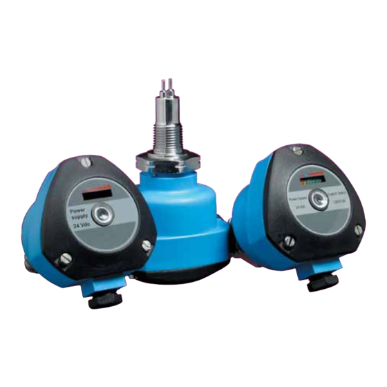
® Introduction FSW6000/7000 Thermal Dispersion Flow Switch Monitor The FSW series of thermal flow switches is designed to monitor flow status of liquids and gases and can also be used to detect level. A chain of 8 LED's gives the user a visual indication of the flow status of the switch. There are two red LEDs that indicate whether or not the unit has detected flow, a yellow LED to indicate the set point (for increasing or decreasing flows) and 5 green LEDs that indicate the amount of flow beyond the set point of the unit. -
Page 5: Models & Dimensions
Other insertion lengths are available upon request Process Connections ANSI 150# Threaded Connections Tri-Clamp Connection Flange Connections ANSI 300# 1” ½” 1” 1 ½” 1 ½” 3/4” TC Connection Rubber Seal 1” 2” 2” Process Connection 1 ½” 2 ½” 2 ½” 1,75 www.omega.com e-mail: info@omega.com... -
Page 6: Wiring Diagram
® Wiring Diagram Nylon Housing FSW6000 - AC Powered M12 Connector Optional Bargraph (B1) Central LED (L1) (Red/Green) NO or NC contact Adjust Connector 12mm 2000mm Adjust (P1) - Power Supply Power Supply 3 - NO Contact 4 - NC Contact Common Power Supply... - Page 7 Power Supply 100 % Flow 3 - Ground 4 - NO Contact 5 - Common 1 2 3 4 5 6 NC Contact Adjust (P1) 7 - NO Contact 8 - Common 9 - NC Contact 2SPDT www.omega.com e-mail: info@omega.com...
-
Page 8: Fsw Relay Status Guide
® FSW Relay Status Guide Application Set Point LED Status FSW SPDT Condition Status NO (4) NC (6) Normal C (5) NO (4) NC (6) GREEN Alarm C (5) Application Set Point LED Status FSW SPDT Condition Status NO (4) NC (6) GREEN Normal... -
Page 9: Pre-Installation
FSW unit. 5) Verify that the operating pressure and temperature of the process corresponds to the operating parameters of the FSW unit. More recommendations and handling instructions can be found on page 14. www.omega.com e-mail: info@omega.com... -
Page 10: Installation
® Installation Installation: Fig. 1 The FSW may be installed in a pipe using a Flow Switch with “T”connection (see fig. 1) or inserted directly into “T” connection the pipe (see fig. 2). The site might need to adapt the installation so that it conforms with the following recommendations. -
Page 11: Calibration
It is important to determine the specific set point at which the flow switch should activate or de-activate. Adjust Adjust Set Point Set Point 100% 100% BARGRAPH - Lights OFF BARGRAPH - Lights ON BARGRAPH - Lights ON BARGRAPH - Lights OFF www.omega.com e-mail: info@omega.com... - Page 12 Calibration To Activate The Switch On Increasing Flow: 1 - Set the flow rate to the desired set point and allow it to stabilize for 2 minutes. 2 - Turn the potentiometer counter-clockwise until the central LED turns red. 3 - Turn the potentiometer clockwise until the central LED changes to a blinking green. 4 - Continue to turn the potentiometer clockwise until the first 2 green LEDs in the bar graph turn on.
-
Page 13: Handling
Care should be taken when handling and installing probes with coated rods to avoid scratching them. Scratching the coating could interfere with the probe performance. Fig. 4 When cleaning the rod use a soft brush or any other similar object. Fig. 5 www.omega.com e-mail: info@omega.com... -
Page 14: Technical Specifications
® Technical Specifications FSW6000 Adjust Flow 100 % 1 2 3 4 5 6 Adjust Nylon Housing Aluminum Housing Aluminum Housing Flow for liquids and gas level for liquids only Application Operating Voltage 85-240Vac (50/60hz) or 125Vdc +/- 100mA Current Consumption Relay(SPDT) 5A - 250Vac for Nylon and Small Aluminum Housing Output (2 SPDT Large Aluminum Housing) - Page 15 Process Connection 316 Stainless Steel Wetted Material 14 to 176º F (-10 to 80ºC) sanitary option to 248ºF (120ºC) Operating Temperature 1450 PSI (100 Bar) /4500 PSI (300 Bar) upon request Max Pressure Class Protection IP 65 www.omega.com e-mail: info@omega.com...
-
Page 16: Trouble Shooting
LED doesn’t change color Verify the calibration Flow switch Radio frequency Use armored cable turns on or interference and shielded housing off suddenly Relay remains Sensor is potentialy Contact Omega or your closed defective local representative for further instruction... - Page 18 M-3993/1014...
Need help?
Do you have a question about the FSW-6000 Series and is the answer not in the manual?
Questions and answers