Table of Contents
Advertisement
Quick Links
Where Do I Find Everything I Need for
Process Measurement and Control?
OMEGA...Of Course!
Shop online at omega.com
TEMPERATURE
Thermocouple, RTD & Thermistor Probes,
Connectors, Panels & Assemblies
Wire: Thermocouple, RTD & Thermistor
Calibrators & Ice Point References
Recorders, Controllers & Process Monitors
Infrared Pyrometers
PRESSURE, STRAIN AND FORCE
Transducers & Strain Gauges
Load Cells & Pressure Gauges
Displacement Transducers
Instrumentation & Accessories
FLOW/LEVEL
Rotameters, Gas Mass Flowmeters & Flow Computers
Air Velocity Indicators
Turbine/Paddlewheel Systems
Totalizers & Batch Controllers
pH/CONDUCTIVITY
pH Electrodes, Testers & Accessories
Benchtop/Laboratory Meters
Controllers, Calibrators, Simulators & Pumps
Industrial pH & Conductivity Equipment
DATA ACQUISITION
Data Acquisition & Engineering Software
Communications-Based Acquisition Systems
Plug-in Cards for Apple, IBM & Compatibles
Datalogging Systems
Recorders, Printers & Plotters
HEATERS
Heating Cable
Cartridge & Strip Heaters
Immersion & Band Heaters
Flexible Heaters
Laboratory Heaters
ENVIRONMENTAL
MONITORING AND CONTROL
Metering & Control Instrumentation
Refractometers
Pumps & Tubing
Air, Soil & Water Monitors
Industrial Water & Wastewater Treatment
pH, Conductivity & Dissolved Oxygen Instruments
All manuals and user guides at all-guides.com
M-4465/0707
Multi-Point Ultrasonic Level Switch
User's Gui d e
http://www.omega.com
e-mail: info@omega.com
LVCN700 Series
®
Advertisement
Table of Contents

Subscribe to Our Youtube Channel
Related Manuals for Omega LVCN700 Series


Summary of Contents for Omega LVCN700 Series
- Page 1 All manuals and user guides at all-guides.com Where Do I Find Everything I Need for Process Measurement and Control? User’s Gui d e OMEGA…Of Course! Shop online at omega.com TEMPERATURE Thermocouple, RTD & Thermistor Probes, Connectors, Panels & Assemblies Wire: Thermocouple, RTD & Thermistor Calibrators &...
-
Page 2: Specifications
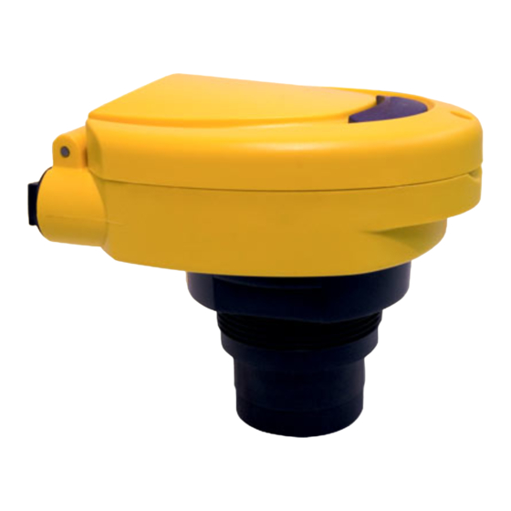
All manuals and user guides at all-guides.com SPECIFICATIONS Step One LVCN700 Series Range: LVCN704: 2" to 4' (5 cm to 1.2m) Enclosure (Top View) LVCN709: 4" to 9.8' (10 cm to 3m) LVCN716: 4" to 16.4' (10 cm to 5m) LVCN126: 8"... -
Page 3: Material Compatibility
OMEGA recommends the use of redundant backup systems and alarms in addition to the primary system. Flammable, Explosive or Hazardous Applications: The LVCN700 series should not be used within classified haz- LVCN726 Shown RELAY RELAY... - Page 4 A. Supply Voltage: The power supply voltage should never exceed A. Introduction: The switch has two modes, the RUN and CAL the maximum rating of 250 VAC for the LVCN700 series AC switch modes. In the RUN mode, the switch is operational and the relay(s) or 28 VDC for the LVCN700-DC series switch.
- Page 5 DC version), tape measurer, flat reflective target such as a wall, and = distance two and D3 = Distance 3) per the following logic. optional Omega box insert for use as a product holder. Relay Function Button Sequence @ Distance(s) C.
- Page 6 All manuals and user guides at all-guides.com PROGRAMMING PROGRAMMING Step Eight Step Nine C. Programming a High and Low Level Out of Bounds D. Programming Automatic Fill: After having powered the Alarm: After having powered the switch with the appropriate supply switch with the appropriate supply voltage, entered the CAL mode, voltage, entered the CAL mode, selected a relay channel and erased selected a relay channel and erased any previously input set points,...
- Page 7 All manuals and user guides at all-guides.com PROGRAMMING PROGRAMMING Step Ten Step Eleven E. Programming Automatic Empty: After having powered the Programming Duplexing Pump Control: After having powered switch with the appropriate supply voltage, entered the CAL mode, the switch with the appropriate supply voltage, entered the CAL selected a relay channel and erased any previously input set points, mode, selected relay channel 1 and erased any previously input set follow the below procedure:...
-
Page 8: Installation
All manuals and user guides at all-guides.com PROGRAMMING INSTALLATION Step Twelve Step Thirteen Programming Duplex Pump Control (continued): Do not install at Do not install with- Duplex Programming angle relative in 3” of (Backup) to the liquid tank side wall Set Point Insert Tape... -
Page 9: Troubleshooting
The RED Relay LEDs will be ON or OFF as programmed per the cur- when actuating pumps or valves. rent level state. A. Wiring a LVCN700 series (95-250 VAC) to a Pump (Automatic Fill or Empty) and (Independent High and Low) RELAY... -
Page 10: Operation
All manuals and user guides at all-guides.com OPERATION Step Sixteen Functional Chart for Relay On/Off Operations Backup Primary Duplexing Control Stop Operation Energize Relay 1 De-Energize Energize Relay 2 De-Energize Backup Alternating Primary Control Operation Stop Energize Relay 1 De-Energize Energize Relay 2 De-Energize...
Need help?
Do you have a question about the LVCN700 Series and is the answer not in the manual?
Questions and answers