Advertisement
Quick Links
Advertisement

Related Manuals for Omega TF280-N


Summary of Contents for Omega TF280-N
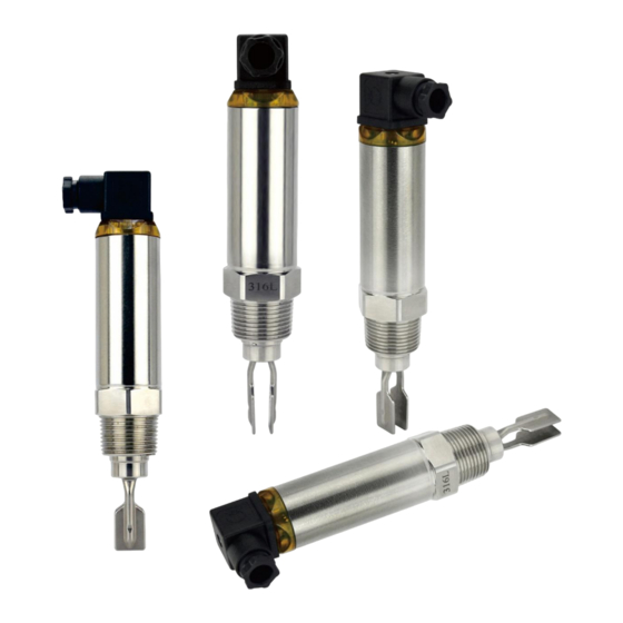
- Page 1 TF280-N/ TF280-P Tuning Fork Level Switch...
-
Page 3: Table Of Contents
Contents 1. Models …………………………………………………………………….……….……4 2. Wiring …………………………………………………………………….….…………5 3. Fork Sensing Spot ......................6 4. Magnetic Test ........................ 6 5. Output Status ........................ 7 6. Installation...……………………………………………………………………………8 7. Simple Troubleshooting ..................... 9... -
Page 4: Models
1. Models... -
Page 5: Wiring
2. Wiring Power supply is DC. Output is PNP / NPN. Please see Figure 1. DIN & Cable Wiring: PNP Output: High(Max.) Mode: No. 1 pin(Brown) is connected to N-. No.3 pin(Blue) is connected to L+. Output is connected to No. 2 pin(Black), then connected to N-. -
Page 6: Fork Sensing Spot
3. Fork Sensing Spot TF280-N/TF280-P fork sensing spot is shown as Figure 3 below. Considering testing medium is water (S.G.=1 g/cm ) , sensing spot is at the fillister about 23mm from the tip. If testing medium has S.G. lower than 1g/cm , sensing spot would be above the fillister. -
Page 7: Output Status
5. Output Status TF280-N/TF280-P is equipped with 12~55 Vdc, top of housing would light up with green LED. DIN & Cable type: Low(Min.) Mode: Tuning fork switch will be actuated 3 seconds after the power is on. Relay is NO and red LED indication is on. When tuning fork is covered by testing medium, vibration stops and relay becomes NC. -
Page 8: Installation
6. Installation Horizontal Installation: 1. Can be applied in viscosity, powder and, liquid. Do not inst.( Figure 1) 2. When installing the product, The position hole plug must be upward direction. If not, incorrect installation could be damage the product.( Figure 2) (Figure 1) (Figure 2) Vertical Installation:... -
Page 9: Simple Troubleshooting
7. Simple Troubleshooting Error Cause Solution Power on or check the wiring Power Supply indicator No power supply. and repair. (Green Light) is off and the switch is not Power doesn't meet the Check the nameplate and conductive. specification. power 12 to 55 Vdc The control circuit wiring Check the wiring diagram The signal lamp is... - Page 11 M5733/0119...
Need help?
Do you have a question about the TF280-N and is the answer not in the manual?
Questions and answers