
Subscribe to Our Youtube Channel
Related Manuals for Omega FLSW3400 Series


Summary of Contents for Omega FLSW3400 Series
- Page 1 User’ s Guide Shop online at www.omega.com e-mail: info@omega.com FLSW3400 & 3500 Series Optical Sensor Switch...
- Page 2 Toll Free in United Kingdom: 0800-488-48 FAX: +44 (0)161 777 6622 e-mail: sales@omega.co.uk It is the policy of OMEGA to comply with all worldwide safety and EMC/EMI regulations that apply. OMEGA is constantly pursuing certification of its products to the European New Approach Directives.
-
Page 3: Table Of Contents
TABLE OF CONTENTS UNPACKING the Optical Sensor Switch ----------------------- 1 1.1 Inspect Package for External Damage ........1 1.2 Unpack the Optical Sensor Switch.......... 1 1.3 Returning Merchandise for Repair .......... 1 DESCRIPTION----------------------------------------------------------- 2 INSTALLATION --------------------------------------------------------- 2 3.1 Electrical Connections ............2 4. -
Page 5: Unpacking The Optical Sensor Switch
1.2 Unpack the Optical Sensor Switch Open the carton carefully from the top and inspect for any sign of concealed shipping damage. Please keep all packing and notify Omega Customer Service of any damage. When unpacking the instrument please make sure that you have all the items indicated on the Packing List. -
Page 6: Description
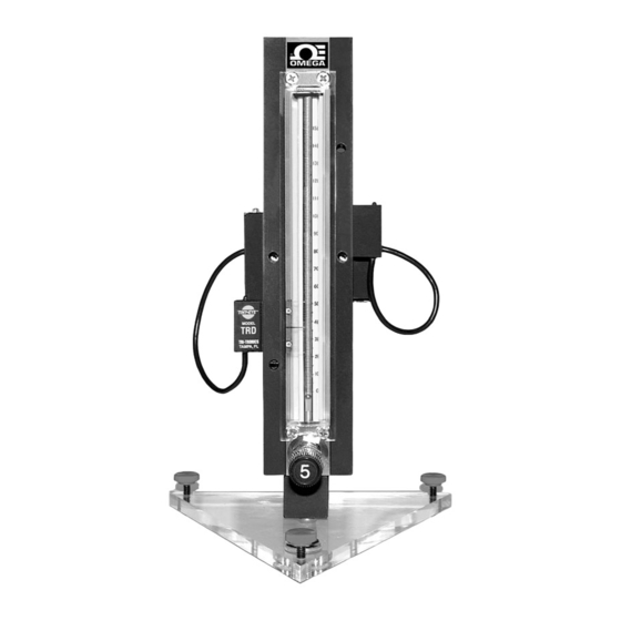
2. DESCRIPTION The 150mm High /Low Alarm Flow Meter with Optical Sensor Switch is a noninvasive means for detection of a HI or LOW flow. This sensor is ideal for signaling an alarm, cutoff valve, or other device when the float passes the detector. A small LED sensor and receiver are mounted on one side of the flow meter. - Page 7 side of the Optical Sensor Switch. Alternatively power can be connected via the DC power jack on the bottom side of the unit. If you are using your own power supply, be sure that the voltage level is between +12 and +15 Vdc. SUPPLYING DC POWER TO THE POWER JACK AND THE "D"...
-
Page 8: Specifications
The power input is protected by a 600mA M (medium time-lag) resettable fuse. If a shorting condition or polarity reversal occurs, the fuse will cut power to the valve circuit. Disconnect the power to the unit, remove the faulty condition, and reconnect the power. The fuse will reset once the faulty condition has been removed. -
Page 9: Ce Compliance
5. CE Compliance Any model Optical Sensor Switch bearing a CE marking on it, is in compliance with the below stated test standards currently accepted. EMC Compliance with 89/336/EEC as amended; Emission Standard: EN 55011:1991, Group 1, Class B Immunity Standard: EN 55082-1:1992 6. -
Page 10: Sensor Alignment
ALARM DIP SWITCH CONFIGURATION LEFT RIGHT ACTION WHEN SWITCH ALARM ALARM IS” ON” LED and Relay are On (LATCH) BUZZER is On (LATCH) LED and Relay are On momentary (FOLLOW SENSOR) BUZZER is On momentary (FOLLOW SENSOR) Figure 6.1, Optical Sensor DIP Switch Configuration. Each Optical Sensor Switch is shipped from the factory with the retro reflective sensors aligned and does not require additional adjustment of the focus distance. -
Page 11: Troubleshooting
7. TROUBLESHOOTING 7.1 Common Conditions Your Optical Sensor Switch was thoroughly checked at numerous quality control points during and after manufacturing and assembly operations. It was carefully packed to prevent damage during shipment. Should you feel that the instrument is not functioning properly please check for the following common conditions first: Are all cables connected correctly? Are there any leaks in the installation? -
Page 12: Troubleshooting Guide
For best results it is recommended that instruments are returned to the factory for servicing. See section 1.3 for return procedures. 7.3 Technical Assistance Omega Engineering will provide technical assistance over the phone to qualified repair personnel. Please call our Technical Assistance at 800-872-9436 ext. -
Page 13: Appendix 1
APPENDIX 1 COMPONENTS DIAGRAM APPENDIX 2 DIMENSIONAL DRAWINGS 2.01 2.22 2.20 1.00 3.00 NOTES: Omega reserves the right to change designs and dimensions at its sole discretion at any time without notice. For certified dimensions please contact Omega... - Page 15 Department will issue an Authorized Return (AR) number immediately upon phone or written request. Upon examination by OMEGA, if the unit is found to be defective, it will be repaired or replaced at no charge. OMEGA’s WARRANTY does not apply to defects resulting from any action of the purchaser, including but not limited to mishandling, improper interfacing, operation outside of design limits, improp- er repair, or unauthorized modification.
- Page 16 Where Do I Find Everything I Need for Process Measurement and Control? OMEGA… Of Course! Shop online at www.omega.com TEMPERATURE Thermocouple, RTD & Thermistor Probes, Connectors, Panels & Assemblies Wire: Thermocouple, RTD & Thermistor Calibrators & Ice Point References Recorders, Controllers & Process Monitors...
Need help?
Do you have a question about the FLSW3400 Series and is the answer not in the manual?
Questions and answers