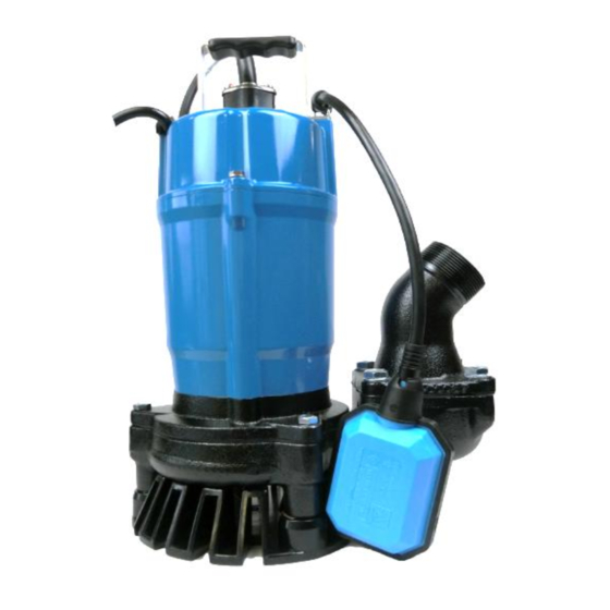
Tsurumi Pump HS Series Overhaul Manual
Hide thumbs
Also See for HS Series:
- Operation manual (17 pages) ,
- Starting and operating instruction (59 pages) ,
- Starting and operating instructions (45 pages)
Advertisement
Quick Links
Advertisement

Subscribe to Our Youtube Channel
Related Manuals for Tsurumi Pump HS Series


Summary of Contents for Tsurumi Pump HS Series
- Page 1 OVERHAUL MANUAL HS series...
- Page 2 Release from Liability Upon reading this, the user of the respective Tsurumi product and Overhaul Manual acknowledges and understands Tsurumi Europe shall not be held liable for any user injury that occurs during the inspection and disassembly/assembly of the product. The users also acknowledge that they will be held responsible for any damage or destruction inflicted onto the product, and/or for the loss of parts during inspection and self-performed maintenance.
- Page 3 HS(A)2.4S-52 | HS(A)3.75S-52 | HSD2.55S-53 The following is a guideline for the overhaul of the 0.4kW and 0.75kW Tsurumi HS series submersible pumps. Use this guide, along with the parts list, exploded view diagram, and operation manual for your particular pump model to disassemble, inspect, and rebuild your pump to factory conditions.
- Page 4 Exploded View (Reference: HS2.4S-52)
-
Page 5: Table Of Contents
Sections • Insulation Resistance Testing Page • Prepare for Disassembly Page • Inspect Wet End for wear Page • Inspect Oil Chamber Page • Inspect Mechanical Seal Page • Motor Inspection Page • Pump Re-Assembly Page... - Page 6 Tools Required...
-
Page 7: Insulation Resistance Testing
Electrical Testing Perform proper electrical testings. Please refer to the operation manual. All electrical work must be performed by an authorized electrician only in compliance with local electrical equipment standards and internal wiring codes. Never allow an unauthorized person to perform electrical work because it is not only against the law, but it can also be extremely dangerous. - Page 8 Cable Inspection Measure and inspect pump cable. If there are any cuts or other deformities in the cable, or the cable is less than the original length, the cable should be replaced. Inspect cable plug for damage and ensure that grounding prong is intact for safe operation.
-
Page 9: Prepare For Disassembly
Prepare for Disassembly With a paint pen or marker, make orientation marks on the strainer, oil casing, and outer cover to ensure proper orientation upon re-assembly. - Page 11 Motor Casing Visual Inspection Remove the two bolts securing the cable gland to the outer cover. Carefully wiggle the cable assembly out of the motor casing and inspect the connections. If there is oil and/or water present in this area, the motor assembly will need to be disassembled for inspection and repair.
- Page 12 Head Cover Disassembly Disconnect the three bullet connectors that connect the cable to the motor stator. Bullet Connectors Remove handle, and set the cable aside. (Disconnected) Remove the motor head cover. Packing A deformation in the outer cover can cause water to leak at these points, reducing Motor Head Cover performance.
- Page 13 Cable Inspection With the cable disconnected, it may be useful to carefully examine the disconnected bullet connectors for any damage. For the HSA pumps, inspect the float and the cable to which it is attached.
- Page 14 Test Capacitor Using wire cutters, cut the zip ties securing the wires going to the capacitor. Remove the lead wires from the capacitor. To avoid injury, discharge the capacitor by attaching the leads of your multi-meter to the leads of the capacitor while in Voltage AC setting.
- Page 15 Test Capacitor Capacitor The HS(A)3.75S pumps reveal a different motor bracket once the motor head cover is removed. These pumps’ motor head bracket contains a motor protector, and a different style capacitor. Remove the leads connecting to the capacitor. To avoid injury, discharge the capacitor by attaching the leads of your multi-meter to the leads of the capacitor while in Voltage AC setting.
-
Page 16: Inspect Wet End For Wear
Inspect Pump Casing for Wear and/or Debris If your pump motor is running but is not performing as new, there could be wear to the impeller and wear plate or foreign debris stuck in the strainer or pump casing. - Page 17 Remove Lower Portions To begin removal of the strainer stand and pump casing, remove the nuts from the bolts located on the oil casing. Oil Casing Bolts (nuts removed)
- Page 18 Remove Lower Portions With the nuts removed, the pump may be lifted off of the pump casing and strainer stand. The bolts do not need to be removed from the lower portion for this. Inspect the strainer, pump casing, and hose coupling for any wear or damage.
- Page 19 ( REFERENCE ) HSD2.55S Pump Casing Pump End Disassembly Strainer Stand...
- Page 20 Remove Discharge Coupling Hose Coupling For further inspection of the pump casing and hose coupling, the two may be separated by removing the nuts, washers, and bolts. If there is any wear or damage to either components they may be replaced to improve pump performance.
- Page 21 Agitator Washers Remove Impeller To remove the impeller, the pump will need to be placed upside down. If the motor head cover was removed prior to this point, it is recommended to place the pump on some form of support (like wooden blocks) so that the pump does not rest on the cables or capacitor on the top of the pump.
-
Page 22: Inspect Oil Chamber
Inspect Oil Chamber It is recommended to inspect the oil every 6 months of operation. If there is water in the oil chamber or the oil level is low, this is evidence of a worn mechanical seal, which should be replaced before irreparable damage or bodily injury occurs. - Page 23 Drain and Inspect Oil Oil Plug To drain the oil, remove the oil plug and its packing, located on the side of the oil casing. Oil casing may be under pressure, so be sure to wear eye protection, and shield the oil from spraying everywhere.
-
Page 24: Inspect Mechanical Seal
Inspect/Remove Mechanical Seal If oil or debris was found in the oil chamber, or oil level is low, it is necessary to change the mechanical seal. - Page 25 Remove Oil Casing If there is evidence that mechanical seal is leaking (water or debris in the oil or motor has failed the Megger test), it will be necessary to remove the oil casing from the motor frame. Using a hex bit, remove the (3) bolts securing the oil casing.
- Page 26 Inspect Oil Casing, O-ring, Oil Lifter, and Mechanical Seal. It is recommended to use only new packings and O-rings upon re-assembly, so O-ring will NOT be re-used. Check for debris, or grit in the Oil Chamber, and make sure Oil Lifter is not cracked or otherwise damaged.
- Page 28 Remove Oil Lifter The oil lifter is press-fit into the oil casing. Oil Lifter Carefully lift this off to allow removal of the stationary portion of the mechanical seal. The stationary seal may be tapped out of the oil casing using a tool with similar diameter. Oil Casing...
- Page 30 Remove Lower Mechanical Seal With two flat blade screwdrivers, CAREFULLY pry the upper portion of the rotary mechanical seal up and remove this face along with the spring. Take care not to damage the rotor shaft with the screwdrivers.
- Page 31 Remove Upper Mechanical Seal With the lower seal and spring removed, then remove the upper seal. Take care not to damage the rotor shaft with the screwdrivers. The bottom of the mechanical seal may be identified by the rectangular indentation...
-
Page 32: Motor Inspection
Motor Inspection If your pump is tripping a circuit breaker or other device, this is evidence of an internal short in the motor or the cable. If your pump is making abnormal grinding noises or doesn’t spin, this is evidence of damaged bearings. Both would require disassembly and inspection of the motor components. - Page 33 Remove Motor Bracket Place the motor on its side and tap the end of the shaft with a RUBBER OR PLASTIC hammer. (A metal hammer can cause damage to the shaft end not allowing the impeller to be replaced.) Place the motor upright and remove the motor bracket, taking care while pushing Motor the wires through the bracket.
- Page 34 Inspect Rotor, Stator and Bearings Stator Spin bearings. If bearings appear to wobble or spin rough, they should be replaced. A bearing puller and bearing heater will be necessary for proper disassembly/assembly If stator does not visibly have evidence of being burned, but is wet from oil or water, it will need to be cleaned with compressed air/mineral spirits and baked...
- Page 35 ( REF.: for HS2.4S )
- Page 36 Remove Upper Stationary Seals Using a punch the same size as the seal, carefully tap it out of the casing onto a soft surface, or use a flat-head screwdriver to carefully lift the seal out. The seal will not be re-used, but in case of inspection, don’t crack or damage it.
- Page 37 Inspect All Components for Replacement With disassembly complete, inspect all the components for wear or damage, and make a list of components that will need to be replaced. All Packings and O-rings should be replaced along with the mechanical seal and oil. For all other parts, use your discretion.
-
Page 38: Pump Reassembly
Pump Reassembly Once all components have been verified to be in operable condition, we can now re-assemble the pump. New O-Rings and Packing materials are available as a kit, and should always be used upon re-assembly... - Page 39 Lay Out Mechanical Seal for Proper Placement It is very important that the mechanical seal components are oriented properly when installed. This is how they should appear on the shaft. Left to right = Top to bottom. Rectangular Indentation Upper Mechanical Seal Lower Mechanical Seal (Motor Side) (Impeller Side)
- Page 40 Reassemble Stationary Seals Coat mechanical seal components with fresh oil. Carefully press upper stationary mechanical seal (ceramic) into motor frame, and press lower stationary seal (SiC) into the oil casing. Ensure seals are properly seated and sitting parallel to the casings. Press oil lifter into oil casing.
- Page 41 Reassemble Motor Place rotor assembly back into motor frame/stator assembly. Place wave washer back onto top of upper bearing.
- Page 42 Reassemble Motor Be sure to re-align the motor bracket and packing per the alignment marks drawn previously.
- Page 43 Secure Motor Assembly Re-install capacitor and attach leads from stator. For the HS2.4S pumps, the blue wire goes on the left (single lead), and black is on the top right, and red wire is bottom right. For the HS3.75S pumps, the red and black wires are connected to the motor protector, and one blue wire is connected to the motor protector and capacitor, and the other blue wire is connected to the capacitor and the motor frame wiring.
- Page 44 Reassemble Rotary Seals Coat rotor shaft with oil and carefully press upper rotary seal (motor side) onto shaft until it touches the upper stationary seal. Place spring against rotary seal, and press lower rotary seal (chamfered edge – impeller side) on the shaft. * Placing the pump upside down on a support (to protect the wires and capacitor) Recall the bottom part of the mechanical seal can be identified by the rectangular indentation located on its side.
- Page 45 Reassemble Oil Casing Insert the motor housing seal into the oil casing, with the “white wall” facing the dry side of the casing. Insert the oil lifter onto the seal and make sure it is firmly in place. Placing the pump upside down on a support (to protect the wires and capacitor), slide the oil casing on to the rotor.
- Page 46 Re-assemble wet end Place V-ring and shaft sleeve assembly onto motor shaft with flat face of the shaft sleeve away from motor and rubber V-ring towards the motor. Then replace the impeller. Secure impeller with flat washer, lock washer and agitator. V-ring &...
- Page 47 Reassemble Pump Casing Secure the hose coupling to the pump casing with the washers, nuts, and bolts, and ensure the hose coupling is in the correct direction by referencing the provided image. (HSD Pump Casing)
- Page 48 Reassemble wet end Ensure that the correct packing is firmly attached to the oil casing. Slide the pump casing onto the bolts of the strainer stand, and then slide the rest of the pump back on to the pump casing and bolts of the strainer stand.
- Page 49 Reassemble motor head cover Place the motor head cover over the capacitor and top of the pump. Be careful to pull the wires through the gland of the motor head cover. Secure the cover with the hex bolts. Ensure proper direction of the cover before securing it. Connect the wires protruding from the gland of the motor head cover to those of the cable via bullet connectors.
- Page 50 Reassemble Top End Gently push the wires and the bullet connectors into the motor head cover through the hole, and slide the metal gland over the rubber end of the cable. Secure in place with the hex bolts.
- Page 51 Reattach Handle Before securing the handle to the motor head case, ensure the rubber cable clip and cable are in their correct positions. The shown position of the cable is necessary to relieve stress from the cable and wire connections (under the gland) when in tension. Secure the handle with the hex bolts.
- Page 52 Air Tightness Test Oil Casing With an air tight fitting, test if the mechanical seal is seated properly. If the chamber can hold for more than 1 minute, the seal is seated properly and will not leak.
- Page 53 Replace Oil Provide the pump with new oil by placing it on its side, remove the oil plug, and carefully pour in the correct amount of oil. Close the oil plug.
- Page 54 Perform Run Test Connect pump cable to single phase power with correct voltage on the nameplate. Make sure pump is pushing air and there is no abnormal noises coming from the unit. Pump should make a steady humming sound when running. If there are any questions, feel free to contact us at sales@tsurumi.eu...
- Page 55 OVERHAUL MANUAL HS series...
Need help?
Do you have a question about the HS Series and is the answer not in the manual?
Questions and answers