Icom IC-718 Basic Manual
Hf all band transceiver
Hide thumbs
Also See for IC-718:
- Service manual addendum (206 pages) ,
- Instruction manual (87 pages) ,
- Service manual (54 pages)
Table of Contents
Advertisement
Quick Links
Advertisement
Table of Contents

Related Manuals for Icom IC-718


Summary of Contents for Icom IC-718
- Page 1 BASIC MANUAL HF ALL BAND TRANSCEIVER |718...
-
Page 2: Important
• Force majeure, including, but not limited to, fires, earthquakes, storms, floods, lightning, or other natural could cause a fire or damage the transceiver. disasters, disturbances, riots, war, or radioactive contamination. • The use of Icom transceivers with any equipment that is not manufactured or approved by Icom. -
Page 3: Trademarks
Immediately turn OFF the power and/or remove During mobile operation, NEVER place the transceiver the DC power cable. Contact your Icom dealer or where hot or cold air blows directly onto it. distributor for advice. -
Page 4: Table Of Contents
Setting the frequency ........... 9 CAUTION: Changes or modifications to this device, Dial Lock function ..........9 not expressly approved by Icom Inc., could void RF gain and SQL level ........10 your authority to operate this device under FCC Meter display selection ........ -
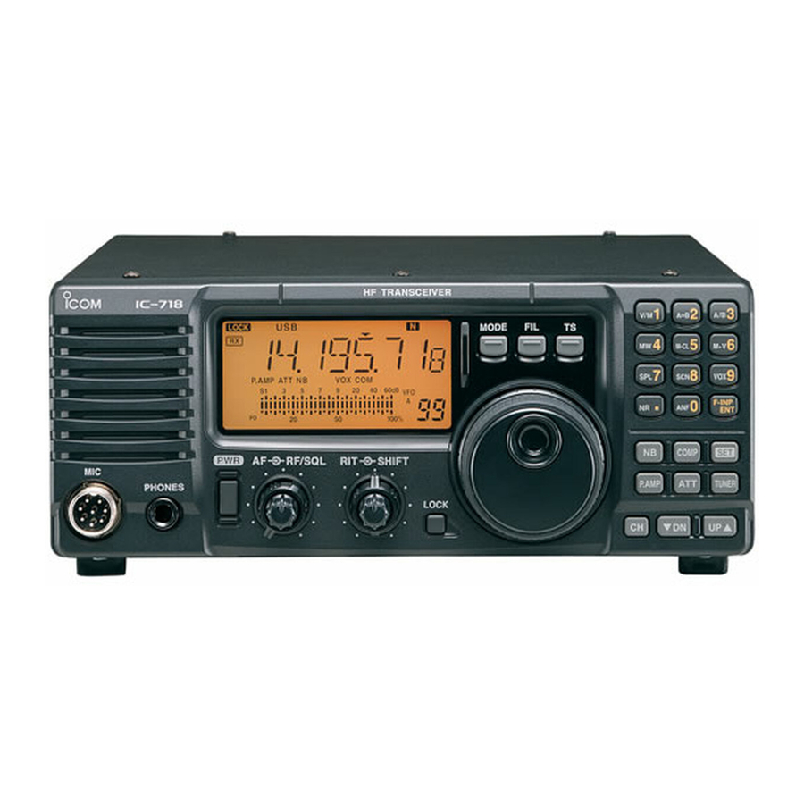
Page 5: Panel Description
PANEL DESCRIPTION Front panel Speaker Function display 1 POWER SWITCH [PWR] 8 LOCK SWITCH [LOCK] (p. 9) z Push to turn ON the transceiver. Push to turn the Dial Lock function ON or OFF. L Confirm the external DC power supply is ON. L The Dial Lock function electronically locks the [MAIN z Hold down for 1 second to turn OFF. - Page 6 PANEL DESCRIPTION Front panel 15 SET SWITCH [SET] The secondary functions for the numeric keys z Hold down for 1 second to enter the Quick Set No./ mode. (p. 18) Secondary Description function z While holding down [SET], push [PWR] to enter VFO/MEMORY (pp.
-
Page 7: Rear Panel
2 PTT SWITCH 8 ALC INPUT JACK [ALC] Push to transmit, release to receive. Connects to the ALC output jack of a non-Icom NOTE: To maximize the readability of your signal, linear amplifier. hold the microphone 5 to 10 cm (2 to 4 inches) -
Page 8: Function Display
PANEL DESCRIPTION Function display 9 SIGNAL/SQL/RF-GAIN METER 1 LOCK ICON (p. 9) • Displays the signal strength while receiving. Displayed when the Dial Lock function is ON. • Displays the relative output power, ALC, or SWR levels while transmitting. (p. 10) 2 RECEIVE ICON (p. -
Page 9: Installation And Connections
(TVI), broadcast interference (BCI) and other In this case, an antenna tuner is helpful to match the problems, ground the transceiver through the transceiver and antenna. The IC-718 has an SWR GROUND terminal [GND] on the rear panel. meter to continuously monitor the antenna SWR. -
Page 10: Connecting An External Dc Power Supply
Connecting an external DC power supply Confirm that the transceiver is OFF before connecting the DC power cable. L When connecting a non-Icom DC power cable, the transceiver needs: • DC 13.8 V (Capacity: At least 18 Amps) • A power supply with an over current protective line, and low voltage fluctuation or ripple. -
Page 11: Basic Operation
BASIC OPERATION When first applying power Turning power ON or OFF Before turning ON your transceiver for the first time, z Push [PWR] to turn ON the transceiver. make sure all connections are correctly made. z Hold down [PWR] for 1 second to turn OFF the transceiver. -
Page 12: Selecting The Mode
L You can inhibit some modes from the selection, if you do not usually operate them. (p. 20) The IC-718 has 2 Variable Frequency Oscillators (VFO), “A” and “B.” Having 2 VFOs is convenient to quickly toggle between 2 frequencies, or for split TIP: About the Band Stacking Register frequency operation (p. -
Page 13: Setting The Frequency
BASIC OPERATION Setting the frequency D Using the Main Dial D Quick Tuning Step 1. Select the desired operating band and operating When the Quick Tuning function is ON, you can mode. change the tuning step to 0.1, 1, 5, 9, 10, or 100 kHz. 2. -
Page 14: Rf Gain And Sql Level
BASIC OPERATION RF gain and SQL level Adjusting the transmit output power The transceiver uses the same control [RF/SQL] to adjust either the RF gain and the squelch. Before transmitting, monitor your selected By default, when the control is set to the 12 o’clock operating frequency to make sure you do not cause position, rotating the control counterclockwise adjusts interference to other stations on the same frequency. -
Page 15: Receiving And Transmitting
RECEIVING AND TRANSMITTING Preamplifiers RIT function The Receiver Incremental Tuning (RIT) function Below the 1.59999 MHz bands The preamp amplifies received signals in the receiver compensates for differences in frequencies of other front end to improve the signal-to-noise (S/N) ratio stations. -
Page 16: If Shift Function
RECEIVING AND TRANSMITTING IF Shift function The IF Shift function electronically narrows the IF shift operation example: passband frequency of the intermediate frequency (IF) • Adjust the [SHIFT] control for minimum and cuts out higher or lower frequency components of interference. -
Page 17: Selecting The If Filter
RECEIVING AND TRANSMITTING Selecting the IF filter The filter selection adjusts the IF bandpass width, as Filter Band width Mode shown to the right. SSB/CW/RTTY: Wide 6 kHz L Each operating mode memorizes the IF filter setting. AM: Normal Standard SSB/CW/RTTY: Normal 2.4 kHz 1. - Page 18 RECEIVING AND TRANSMITTING Selecting the IF filter Choose the appropriate filter for your operating needs. CAUTION: DISCONNECT the DC power cable To use an Optional filter, you need the following steps: before performing any work inside the transceiver • Set an IF bandpass width by replacing the short-pin to prevent an electrical shock or damage to the on the main board.
-
Page 19: Noise Reduction
RECEIVING AND TRANSMITTING Noise Reduction Automatic Notch Filter (ANF) (This function is only for the USA version transceiver.) (This function is only for the USA version transceiver.) The Noise Reduction function reduces random noise SSB mode components and enhances signal audio. Auto Notch automatically attenuates more than 3 beat tones, tuning signals, and so on, even if they are Push [NR] to turn the Noise Reduction function ON or... -
Page 20: Microphone Compressor
RECEIVING AND TRANSMITTING Microphone Compressor VOX function The Voice-operated Transmission (VOX) function SSB mode switches between transmit and receive with your The Speech Compressor increases the average RF voice. This function enables hands-free operation. output power, improving readability at the receiving station. -
Page 21: Memory Channel And Scan
MEMORY CHANNEL AND SCAN Memory channel operation Scan operaiton The transceiver has 101 Memory channels, 99 of D Programmed scan regular memory channels and P1 and P2 for the Repeatedly scans between two scan edge Programmed Scan edge. frequencies. The Memory mode is useful for quickly changing to Enter scan edge frequencies into the P1 and P2 often-used frequencies. -
Page 22: Set Mode
SET MODE Set mode description You can use the Set mode to set infrequently changed values or function settings. The transceiver has 2 set modes, the Quick Set mode and the Initial Set mode. D Quick Set mode operation D Initial Set mode operation 1. -
Page 23: Quick Set Mode Items
SET MODE Quick Set mode items NOTE: The default settings described below are for the USA version transceiver. The default settings may differ, depending on your transceiver version. RF Power (Default: H) Sets the RF output power. • Range: L (minimum), 1 ~ 99, and H (maximum) Mic Gain (Default: 50) Adjusts the microphone gain. -
Page 24: Initial Set Mode Items
SET MODE Initial Set mode items Mode Select Displays or inhibits the mode selection by pushing [MODE]. Push [MODE] to select an operating mode you want to set, and then rotate [MAIN DIAL] to set it ON or OFF. All the operating modes are ON as default. RF/SQL VR (Default: rS) Selects the function of the [RF/SQL] control. - Page 25 Turns the CI-V transceive function ON or OFF. CI-V 731 Mode (Default: oF) When connecting the IC-718 to the IC-735 for transceive operation, you must convert the operating frequency data from 5 bytes to 4 bytes. L Set to “on” when operating the IC-718 with the IC-735.
-
Page 26: Specifications
SPECIFICATIONS D General D Transmitter • Frequency coverage: (Unit: MHz) • Transmit output power: Receiver 0.030000 ~ 29.999999 * SSB, CW, RTTY 2 W ~ 100 W Transmitter 1.800000 ~ 1.999999 * 2 W ~ 35 W 3.500000 ~ 3.999999 * •... -
Page 27: Options
OPTIONS (As of November 2023) Microphones Cables HM-219 hand microphone OPC-599 adapter cable The same as supplied. 13-pin, ACC connector to 7-pin +8-pin ACC SM-30 desktop microphone connectors. SM-50 desktop microphone OPC-2321 control cable To connect the AH-740 Speaker Approximately 6 m, 19.7 feet SP-41 external speaker Antennas Others... -
Page 28: Maintenance
7 the main dial. D Replacing the circuitry fuse The 13.8 V DC from the DC power source is applied to all units in the IC-718 through the circuitry fuse. The fuse is in the MAIN unit. Circuitry fuse (FGB 4A) 1. -
Page 29: Installation Notes
INSTALLATION NOTES INDEX For amateur base station installations, it is recommended Number that the forwards clearance in front of the antenna array is 1 Hz/10 Hz tuning steps ..4 Noise Blanker ....11 calculated relative to the EIRP (Effective Isotropic Radiated Noise Reduction .... -
Page 30: Définitions Explicites
émet une odeur, de la fumée ou un bruit anormal. Contactez votre revendeur ou distributeur PRÉCAUTIONS Icom pour obtenir des conseils. R AVERTISSEMENT ! NE JAMAIS placer l’émetteur- R DANGER TENSION À HAUTES RF ! NE JAMAIS récepteur sur un support instable où... -
Page 31: Information Fcc
• Faire appel au revendeur ou à un technicien radio/TV expérimenté. MISE EN GARDE : Tout changement ou modification, non expressément approuvé par Icom Inc., peut annuler l’autorisation de l’utilisateur à utiliser cet appareil conformément à la réglementation FCC. Pour le Canada : L’émetteur/récepteur exempt de licence contenu dans... - Page 32 How the World Communicates A7768D-1EX Printed in Japan 1-1-32 Kamiminami, Hirano-ku, Osaka 547-0003, Japan © 2023 Icom Inc. Nov. 2023...
Need help?
Do you have a question about the IC-718 and is the answer not in the manual?
Questions and answers