Advertisement
Quick Links
2015-2023 FORD F-150 CREW CAB, 2017-2023 RAPTOR, 2022-2023 F-150
LIGHTNING, 2017-2023 F-250/F350 SUPERDUTY CREW CAB E-STEP
Note-
Installation time averages 3-4 hours.
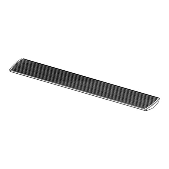
2 Board Assembly
1 Front Motor Linkage Right
1 Rear Motor Linkage Right
1 Rear Motor Linkage Left
1 Front Motor Linkage Left
14 Hexagon Nut M8
14 Large Flat Washer M8
14 Lock Washer M8
8 Socket Cap Screws M6x25mm
INSTALLATION INSTRUCTIONS
PART #FD-4500
25 Wire Ties
2
Fuse
Led Lamp
4
1
Power Board Switch
2
Wire Magnetic Eq Module
4
Wire Magnetic Eq Magnet
1
Controller Assembly
1
Control Input Wire
Page 1 of 16
Advertisement

Related Manuals for Body Armor 4x4 FD-4500


Summary of Contents for Body Armor 4x4 FD-4500
- Page 1 INSTALLATION INSTRUCTIONS 2015-2023 FORD F-150 CREW CAB, 2017-2023 RAPTOR, 2022-2023 F-150 LIGHTNING, 2017-2023 F-250/F350 SUPERDUTY CREW CAB E-STEP PART #FD-4500 Note- Installation time averages 3-4 hours. 2 Board Assembly 25 Wire Ties 1 Front Motor Linkage Right Fuse 1 Rear Motor Linkage Right...
- Page 2 INSTALLATION INSTRUCTIONS Page 2 of 16...
- Page 3 INSTALLATION INSTRUCTIONS Page 3 of 16...
-
Page 4: Product Technical Specification
INSTALLATION INSTRUCTIONS Product Technical Specification Rated Voltage: 12V Specified Load: ≤750lbs Gross Weight: 58lbs Forward Extension Length: 169mm (Horizontal distance between the edge of power board and the vehicle door when the board extends) Board falling dimension: 320mm. (Vertical height difference between the edge of power board and the vehicle door while board extending). - Page 5 INSTALLATION INSTRUCTIONS Mechanical Installation Driver Side Fig 1. Fig 1. As shown in the picture: the three screws on the left rear side are installation spots. Please ensure that the screws are matched with the installation hole of motor linkage. Screw position on the rear left side (Rear Driver side) Fig 2.
- Page 6 INSTALLATION INSTRUCTIONS Passenger Side Step 1: As shown in the picture, fixing the hexagon nut (with spring washer and big washer) into the corresponding screws and tighten it Step 2: As shown in the picture, fixing the hexagon nut (with spring washer and larger washer) into the corresponding screws and tighten it Page 6 of 16...
- Page 7 INSTALLATION INSTRUCTIONS Step 3: Install the board using the M6 x 25 socket cap bolts. Adjust the board at the T- nut to make the two ends of the board sit evenly on the vehicle. Once adjusted, tighten down. Repeat this on the other side. Page 7 of 16...
- Page 8 INSTALLATION INSTRUCTIONS Step 1: Find out the control input wire and pull out the fuse (ensuring circuit safety during installation) and connect the positive and negative pole of wire harness to vehicle battery respectively. Note: Any modifications made to the harness will void warranty. Page 8 of 16...
- Page 9 INSTALLATION INSTRUCTIONS Figure 1 is the wire harness diagram and figure 2 is the installation diagram. When installing the wire harness, make sure the four connectors relate to the four motor linkages by “front right, rear right, front left and rear left”. Step 2: Put the controller assembly into the bolt and then screw the hexagon nut and...
- Page 10 INSTALLATION INSTRUCTIONS Step 4:The arrangement of motor wire and LED lamp wire: Arrange the motor connection wire along the beam as shown in the picture, the motor wire plug extends to motors of linkage. At least, adjust the wire harness to make sure it is tidy and beautiful.
- Page 11 INSTALLATION INSTRUCTIONS Step 5: Open the cover plate of B-pillar on the right side of the vehicle, expose the above part (as shown above), connect the brown signal wire to terminal A of magnetic inductor, loosen the earthing stud D, connect fork type terminal B to the earthing stud, and then tighten the earthing stud.
- Page 12 INSTALLATION INSTRUCTIONS Step 6:Sort out the wire harness and close the panels. The installation of white signal wire on the left side is same with the right side. Step 7: Tear off the double- sided adhesive sticker behind the LED lamp and stick it to the side of the car skirt, The distance (the lamp of the side 560mm,the back...
- Page 13 INSTALLATION INSTRUCTIONS Step 8: Insert back the fuse, assign the wire in order. Check if all the wires are connected well and test if the power board can work normally. If it can work normally, the board installation is completed. (If it cannot work normally, please check the installation of each part.)
- Page 14 INSTALLATION INSTRUCTIONS 1. Function of power board switch Turn off the switch when there is no need for a power board or inconvenience of power board, then the power board will automatically get back and stop working to avoid any impact when use the vehicle.
- Page 15 RGA issued. Once issued the dealer will request the product be returned to BA facilities. • Products purchased through an authorized BA dealer will be refunded and/or credited by that BA dealer. • Warranty contact: help@bodyarmor4x4.com • Return address: Body Armor 4x4, 1050 N. Vineyard Ave. Ontario CA, 91764 Page 15 of 16...
-
Page 16: Troubleshooting Guide
INSTALLATION INSTRUCTIONS Troubleshooting Guide After installing the steps, when the door is opened one motor goes up while the other goes down. Disconnect the motors and swap connections. How do I extend or retract the motor linkages when I am installing these? Make sure your connected to the battery, connect the power to the motors and the disable switch.
Need help?
Do you have a question about the FD-4500 and is the answer not in the manual?
Questions and answers