Advertisement
Quick Links
Install time- 3-5 Hours
PARTS LIST:
2
Board Assembly
1
Front Motor Linkage Left 6188100.1L
1
Front Motor Linkage Right 6188100.1R
1
Rear Motor Linkage Left 6188100.2L
1
Rear Motor Linkage Right 6188100.2R
Rear Motor Linkage Left 6188101.2R
1
(2DR ONLY)
Rear Motor Linkage Right 6188101.2R
1
(2DR ONLY)
2
M8 x 25mm Hex Bolt
M10 x 25mm Hex Bolt (6 is used for 2
8
DR)
2
Fuse
1
Power Switch
2
Wired Magnetic Module
4
LED Lamp (Optional)
4 DOOR CONTROLLER ASSEMBLY
ONLY ONE CONTROLLER ASSEMBLY IS USED FOR INSTALLTION.
Identify the one needed for your Bronco before continuing the installation
INSTALLATION INSTRUCTIONS
2020-Present Ford Bronco 4DR/2DR
PART# FB-4501 FB-4500
Page 1 of 16
4
M10 x 35mm Hex Bolt
2
M8 Lock Washer
2
M8 Large Washer
12 M10 Lock Washer (10 is used for 2 DR)
12 M10 Large Washer (10 is used for 2 DR)
8
M10 X 25mm Hex Socket Cap Screws
M8 Hex Flange Nut
2
2
Plastic Retainer (2DR ONLY)
1 U Bolt Plate (2DR ONLY)
2 Controller Assembly
25 Wire Tie
4 Magnets
1 Control Input Wire
2 DOOR CONTROLLER ASSEMBLY
Advertisement

Related Manuals for Body Armor 4x4 FB-4501


Summary of Contents for Body Armor 4x4 FB-4501
- Page 1 INSTALLATION INSTRUCTIONS 2020-Present Ford Bronco 4DR/2DR PART# FB-4501 FB-4500 Install time- 3-5 Hours PARTS LIST: Board Assembly M10 x 35mm Hex Bolt Front Motor Linkage Left 6188100.1L M8 Lock Washer Front Motor Linkage Right 6188100.1R M8 Large Washer Rear Motor Linkage Left 6188100.2L 12 M10 Lock Washer (10 is used for 2 DR) Rear Motor Linkage Right 6188100.2R...
- Page 2 INSTALLATION INSTRUCTIONS PACKING LIST- Be sure all hardware and components are present before attempting installation Page 2 of 16...
- Page 3 INSTALLATION INSTRUCTIONS Page 3 of 16...
- Page 4 INSTALLATION INSTRUCTIONS Linkage and Board installation Step 1. Locate the 3 holes under the driver side front and rear door. Refer to photo below. Step 2. Prep the linkage components with the proper hardware. Page 4 of 16...
- Page 5 INSTALLATION INSTRUCTIONS Step 3. Using the hardware, mount the linkages. Do not tighten, just tight enough to prevent movement. (Repeat step 1-3 on passenger side) Step 4. Install the boards using the T-Nuts and the M6x25 Socket Cap Screw. Adjust the step board side to side to have it sit evenly on the vehicle.
- Page 6 INSTALLATION INSTRUCTIONS Wiring routing instructions- 4 Door Wiring routing instructions- 2 Door Page 6 of 16...
- Page 7 INSTALLATION INSTRUCTIONS Wiring harness and controller install diagram Step 1. Remove the fuse from the harness for safety. Then connect the positive and negative wire terminals to the battery. Control harnesses cannot be modified. Doing so will void warranty. Step 2. Identify the connectors to their respective motor linkages. Page 7 of 16...
- Page 8 INSTALLATION INSTRUCTIONS Step 3. Begin installing the harness into the proper linkages and terminals using the diagram below. Step 4. (4 Door) Install the controller using the provided M10x25mm hex bolt, flat washer and lock washer. Page 8 of 16...
- Page 9 INSTALLATION INSTRUCTIONS (2 Door) Step 5. LED light installation Run the LED light strip along the harness with the light facing down. Take the time to also tidy up the wiring harness. Apply the same instructions to both sides. Page 9 of 16...
- Page 10 INSTALLATION INSTRUCTIONS Step 6. Pry the sill panel and A-piller panel on the driver side. Step 7. Pull the white and brown signal wire, as well as the power board switch wire through the rubber grommet on the left (driver) side of the vehicle. The white wire must be fed through under the carpet.
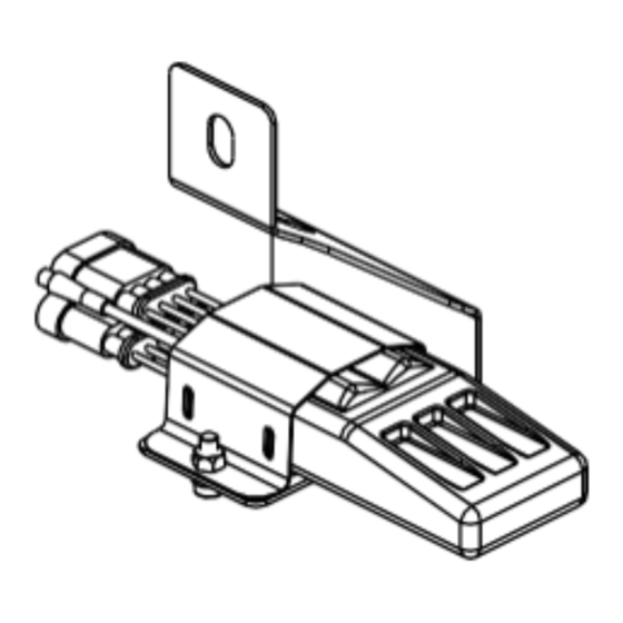
- Page 11 INSTALLATION INSTRUCTIONS Magnetic Inductor installation (4 Door) Step 1. Pry open the B-Pillar on the right side of the vehicle. Connect the brown signal wire to the female insulated terminal A. Loosen the stud D (be sure the stud is clean), connect fork type terminal B to the stud.
- Page 12 INSTALLATION INSTRUCTIONS Magnetic inductor installation (2 Door) Step 1. Open the B-Pillar on the right side of the vehicle. Connect the brown signal wire to terminal A. Loosen the stud on the B-Pillar (be sure its clean), connect the fork type terminal B to the stud. Then tighten it down.
- Page 13 INSTALLATION INSTRUCTIONS Neatly sort the harness and reinstall the panels LED Lighting install Peel the double sided adhesive tape behind the LED lamp and stick it to the thin part of the body below the apron. Page 13 of 16...
- Page 14 INSTALLATION INSTRUCTIONS Connecting the motor wire Connect the connector of the motor with the control input wire harness. Sort out and zip tie the harness along the vehicles body frame. Page 14 of 16...
- Page 15 RGA issued. Once issued the dealer will request the product be returned to BA facilities. • Products purchased through an authorized BA dealer will be refunded and/or credited by that BA dealer. • Warranty contact: help@bodyarmor4x4.com • Return address: Body Armor 4x4, 1050 N. Vineyard Ave. Ontario CA, 91764 Page 15 of 16...
-
Page 16: Troubleshooting Guide
INSTALLATION INSTRUCTIONS Troubleshooting Guide After installing the steps, when the door is opened one motor goes up while the other goes down. Disconnect the motors and swap connections. How do I extend or retract the motor linkages when I am installing these? Make sure your connected to the battery, connect the power to the motors and the disable switch.
Need help?
Do you have a question about the FB-4501 and is the answer not in the manual?
Questions and answers