Advertisement
Quick Links
Advertisement

Related Manuals for Decorotika Cubicco TV Stand


Summary of Contents for Decorotika Cubicco TV Stand
- Page 1 Cub cco TV Stand assembly gu de please scan the QR code for nstallat on v deo...
- Page 2 ntroduct on Before start ng, please check all Furn ture parts are go ng to several Valued Customer, components and accessor es manufactur ng procedures. Dur ng th s accord ng to the prov ded l st. If process, parts can have l ttle dust or We des gn and carefully manufacture our you purchased more than one marks.
-
Page 3: Before You Start
before you start or o Get requ red nstallat on tools prepared. Do not nstall the product on rough surfaces. Get help from someone else! - Page 4 gett ng fam l ar w th the ma n components *Minifix is the main connec on component used in Decoro ka products.Before star ng, please check the below figures MINIFIX MINIFIX SCREW HEAD *Please not ce that there s an small arrow on A02 (m n fix head).Th s arrow should show the d rect on of upper hole.
-
Page 5: Accessory List
ACCESSORY LIST minifix screw 50 mm sticker 12 mm sticker 18 mm sticker minifix head GENERAL VIEW... - Page 6 step a *Please nsert A02 (m n fix head) nto the holes on the p eces #5 and #2 as shown below. *Make sure that all the arrows on A02 (m n fix head) are n correct d rect on. step b *Please nsert A03 (m n fix screw) nto the holes on the p ece #1 as shown below.
- Page 7 step d *Please nsert A03 (m n fix screw) nto the holes on the p ece #3 and #8 as shown below. *Please nsert A02 (m n fix head) nto the holes on the p ece #4 as shown below. *Make sure that all the arrows on A02 (m n fix head) are n correct d rect on.
- Page 8 step g *Please attach the p eces #3 onto the p eces #2 and #4 as shown below *Now screw the A03 (m n fix head) clockw se d rect on w th the help of screwdr ver. step h *Please nsert A03 (m n fix screw) nto the holes on the p ece #1 as shown below *Please nsert A02 (m n fix head) nto the holes on the p ece #2 and #6 as shown below.
- Page 9 step *Please attach the p eces #6 and #2 onto the p ece #1 as shown below. *Now screw the A03 (m n fix head) clockw se d rect on w th the help of screwdr ver. step j *Please nsert A03 (m n fix screw) nto the holes on the p ece #3 and #8 as shown below *Please nsert A02 (m n fix head) nto the holes on the p ece #7 as shown below *Make sure that all the arrows on A02 (m n fix head) are n correct d rect on...
- Page 10 step k *Please attach the p ece #7 onto the p ece #8 as shown below *Now screw the A13 (50 mm screw) clockw se d rect on w th the help of screwdr ver. step l *Please attach the part we nstalled n prev ous step to the p eces #5 as shown below *Now screw the A03 (m n fix head) clockw se d rect on w th the help of screwdr ver.
- Page 11 step m *Please attach the p ece #3 onto the p eces #7 and #2 as shown below. *Now screw the A02 (m n fix head) clockw se d rect on w th the help of screwdr ver.
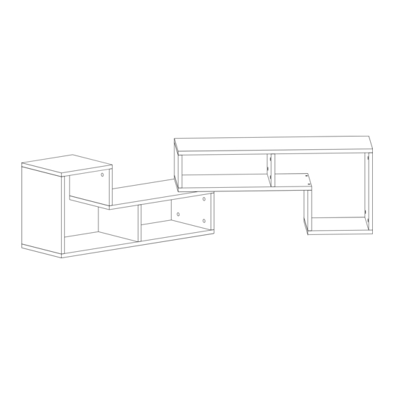
- Page 12 final look step n *For the best appearance of your furn ture please place all A07(12 mm st cker) onto the A13 (50 mm screw). *For the best appearance of your furn ture please place all A06(18 mm st cker) onto the A02 ( m n fix head).
Need help?
Do you have a question about the Cubicco TV Stand and is the answer not in the manual?
Questions and answers