Table of Contents
Advertisement
Advertisement
Table of Contents

Related Manuals for SycoTec easyDive 4425


Summary of Contents for SycoTec easyDive 4425
- Page 1 Operating Manual Frequency Inverter e@syDrive 4425, 4426...
-
Page 3: Table Of Contents
Table of Contents 1.0 User Information 1.1 Symbols Used 1.2 Important Information 1.3 Safety Precautions 1.4 Purpose and Potential Applications 1.5 Specifications Frequency Inverter e@syDrive 4425 1.6 Specifications Frequency Inverter e@syDrive 4426 2.0 Scope of Delivery - Accessories 2.1 Scope of Delivery 2.2 Accessories 3.0 Operational Elements 3.1 Rating Plate... -
Page 4: User Information
Modifications and improvements to the product as a result of new technical developments are possible. This does not imply any right to retrofitting of existing units. SycoTec assumes no responsibility for damage arising through: • external influences (poor quality of the media or faulty installation) •... -
Page 5: Safety Precautions
• In the event of modifications by third parties, the licences become null and void. • Use only SycoTec original parts and spare parts. For safety reasons, the frequency inverter supplied has been configured to operating mode "no motor". Since it is not known which motor will be connected, an incorrect configuration could damage or destroy the motor or the frequency inverter. -
Page 6: Purpose And Potential Applications
The control and monitoring of the inverter are performed by several microprocessors. This ensures high reliability and flexibility. A firmware update can be performed on a PC via a serial interface (RS 232); please contact SycoTec in this context. The frequency inverter can be completely remote-controlled. Various inputs and outputs are freely... -
Page 7: Specifications Frequency Inverter E@Sydrive 4425
1.5 Specifications Frequency Inverter e@syDrive 4425 Configuration via the serial interface using a standard PC Operation via an PLC-compatible remote control or using a standard PC (via the serial interface RS 232) Display lamps for operation (green) H4 and overload (yellow) H5 Dimensions approx. - Page 8 Analogue Inputs FB-N_value U_e = 0 - V, Re = 100 kΩ, I_e = 0,1 mA at 10 V, X6:7 Unwired 0 V, input protected up to max. ±40 V FB+10V U_out = 10 V ±3%, I_out = max. 25 mA, X6:6 FB-Ground Earth reference point for remote control +10V...
-
Page 9: Specifications Frequency Inverter E@Sydrive 4426
1.6 Specifications Frequency Inverter e@syDrive 4426 Configuration via the serial interface using a standard PC Operation via an PLC-compatible remote control or using a standard PC (via the serial interface RS 232) Display lamps for operation (green) H4 and overload (yellow) H5 Dimensions approx. - Page 10 Analogue Inputs FB-N_value U_e = 0 - 10 V, Re = 100 kΩ, I_e = 0,1mA at 10 V, X6:7 Unwired 0 V, Input protected up to max. ±40 V FB+10V U_out = 10 V ±3%, I_out = max. 25 mA, X6 :6 FB-Ground Earth reference point for FB +10 V...
-
Page 11: Scope Of Delivery - Accessories
2.0 Scope of Delivery - Accessories 2.1 Scope of Delivery Frequency Inverter e@syDrive 4425 Material no.1.001.2769 (open version IP 00) or Frequency Inverter e@syDrive 4426 Material no.1.002.2514 (open version IP 00) respectively Frequency Inverter e@syDrive 4425 Material no.1.001.2768 (enclosed version IP 20) or Frequency Inverter e@syDrive 4426 Material no.1.002.2513 (enclosed version IP 20) Connecting cable (9 pin Sub-D plug) -
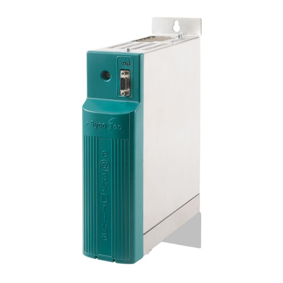
Page 12: Rating Plate
3.1 Rating Plate Position of the rating plates (3) Rating Plate - Open Version (IP 00) Frequency inverter type Serial number Material number Input power Symbols Output power (see chapter 1.1) Frequency inverter type ... -
Page 13: Description Of Function
4.0 Description of Function The minimal output frequency is 30 Hz (1,800 rpm) The maximum output frequency is 4000 Hz (240,000 rpm) for ASM-motors and for DC-motors. The maximum output power is 350 VA (e@syDrive 4425) and 1,000 VA (e@syDrive 4426). The frequency inverter type e@syDrive 4425, 4426 is suitable for the variable-frequency control of various motors, especially with high frequencies of up to 4,000 Hz corresponding 240,000 rpm. - Page 14 Remote Control - Control With External Voltage Supply...
- Page 15 Remote Control - Control Without External Voltage Supply...
-
Page 16: Motor Codes Via Inputs In2
4.5 Motor Codes Via Inputs IN2...IN6 to X5: In order to use IN2...IN6 for the motor codes, code P102 motor coding must be assigned to the number of the motor to be used (1 - 32). Additionally, the required inputs are to be set to motor code with parameters P111–input IN2 up to P115–input IN6 Bit4 Bit3... -
Page 17: Setpoint Value Selection
4.6 Setpoint Value Selection The frequency setpoint value (speed setpoint value) can be predetermined by various sources, and the mode of operation is shown in the following figure. Picture: setpoint value selection In order to use the setpoint value of the PC in P1-N_rated, the "PC application" is set to P7-select operation. -
Page 18: Emergency Motor Stop At Power Failure
To use the fixed value (fixed frequency) in P104 to P106, set P7-select operation to "selection", as well as P142-enabling FF to “remote control". Selection is effected from control inputs IN5 and IN6. If both inputs are on 0 V, then the setpoint value from P1–N_rated or from analogue input AIN1/AIN2 is used –... -
Page 19: Wiring Diagram
4.9 Wiring Diagram... -
Page 20: Assembly And Installation
5.0 Assembly and Installation Before the installation and commissioning of this device, please read the safety and warning information in chapter 1.0 carefully. 5.1 Assembly The frequency inverter e@syDrive 4425, 4426 is designed for mounting in a cabinet: use 2 screws (5mm) for mounting on switch board. Ensure proper electrical connection to protective conductor. -
Page 21: Wiring Guidelines For Compliance With The Emc Standards
5.3 Wiring Guidelines for Compliance with the EMC Standards The inverter was tested according to EMC product standard EN 61800-3 (variable-speed electrical drives). • The above-mentioned EMC product standard can be complied with only by means of shielded motor and control cables. It should be ensured that the cable shields rest over a large area of the inverter housing and are surrounded by the cable clips. - Page 22 X4: Connection Remote Control Connection of digital outputs (Relays) Connection of digital inputs, analogue inputs and frequency outputs X5: Connection PC For Configuration Plug e@syDrive: 9-pin socket Sub-D (1) connecting cable (material no. 1.002.2025)
-
Page 23: Description Of The Operating Software E@Sydrive 4425, 4426
The complete operation and configuration is regulated with the help of a PC. Connecting the frequency inverter e@syDrive 4425, 4426 with the serial interface (COM interface) of the Download of operating software from the SycoTec homepage: www.sycotec.eu -> High-frequency inverters -> Download e@syDrive GUI-Software... - Page 25 Installation of the operating software (via data file: easyDrive_GUI_Installer.msi)
-
Page 27: Operating Software
Start-up of this program via SycoTec_easyDrive.exe Screen display is shown in English language after the first start-up: 7.0 Operating Software 7.1 Operating Language The menu "language choice" offers command to select the installed languages. -
Page 28: Basic Parameters
Generate the corresponding connection by "auto detect" via flag "connection" In exceptional cases it is also possible via manual choice "COM choice". 7.2 Basic Parameters The start page provides the most important operating and display values. The individual parameters are fully described in chapter 8.6. Additional operating windows: •... -
Page 29: Help Data File
7.3 Help Data File For each page there is a help data file, which is activated by clicking on the [help] button. To go back to the previous page, click on [back]. 7.4 Window - Operating Values On this page, the most important operational values are available online (with approx. 1 Hz) – accumulated faults, running times, as well as customer-specified nominal values. -
Page 30: Window - Remote Control
7.5 Window – Remote Control In this window the PLC-compatible remote control interface can be configured. 7.6 Window - Motor Parameters The displayed parameters will change according to the choice of motor connected (parameters for P90 motortype). - Page 31 In accordance with chapter 8.0 Configuration, 32 motor parameter sets can be stored in memory (M1…M32). The following functions can be called up: Motor parameters M1…M32 load Motor parameters M1 - M32 store Motor parameters M1 - M32 delete Load factory setting Load motor parameters...
-
Page 32: Window - V/Hz-Table
7.7 Window - V/Hz-Table When an asynchronous motor is configured , the details can be entered in the V/Hz-Table window and visually controlled. 7.8 Window - Motor Control Parameters The motor control parameters are available in a window underlay: AC-Motor... -
Page 33: Window - Spindle Run-In
DC-Motor 7.9 Window - Spindle Run-in The spindle run-in is only possible if following conditions are complied: - Spindle is stopped - P7 select operation on "PC application" - P110 Input IN1 on "start/stop" - IN1 is connected with +24V (X6:8 to X5:1) Start of the spindle run-in program Cancel of the spindle run-in program... -
Page 34: Window - Specific Programs
7.10 Window - Specific Programs Test of the remote control interface Re-setting parameters to factory settings ASS (After Sales Service) functions... -
Page 35: Configuration
8.0 Configuration All inverter relevant data are accessible in the form of parameters P1 - P150. The configuration is carried out exclusively via the PC operating software. Basic parameters Higher parameters, upon which further adjustments are dependent (P1 / P7 / P8) (speed values, display adjustments, operating language, mode of operation, ...) Display values Pure display values which cannot be changed (P10 - P34) (voltage, current and frequency values) -
Page 36: Specific Programs
8.1 Specific Programs Under special functions, it is possible to establish the default state and to select various utility and test programs which serve as troubleshooting programs and repair aids for the customer and the after sales service (ASS). 8.2 Actuator / Sensor Test This test serves to check the function of the remote control and the internal signal. -
Page 37: Complete Parameter Structure
This function adjusts all parameters P1 … P150 to the original factory settings. After confirming the security question with [OK], the procedure is implemented. Motor parameters stored in memory M1 - M32 are not affected. 8.5 Technical Service Various test programs for the after sales service of SycoTec are accommodated in this section. -
Page 38: Flash Update
8.6 Flash Update This procedure takes a few minutes - please do not interrupt! After successful download following message appears on the screen:... -
Page 39: Parameter List
8.7 Parameter List This list includes all displayable and alterable parameters. In the column "Change/Display", the following abbreviations are used: N = not alterable S = alterable only when motor not running = always alterable, even when motor running M = display and alterability dependent on P90-motortype * = display dependent on other parameters Par. - Page 40 Par. Indication Description Value range, Unit Factory Change/ No. in display physical value setting Display V/Hz characteristic (ASM motor) P60 U0 Start-up voltage at f=0 3% U_nom, 1...50 3% U_nom I M P61 f1 1st characteristic point frequency f_nom, 30...4000 f_nom P62 U1 1st characteristic point voltage...
-
Page 41: Basic Parameters
8.8 Basic Parameters P1 N_rated Rated frequency value (speed pre-selection) for the motor (input on control panel). By means of parameter P8-speed display, this parameter can be changed from frequency display to speed display. The number of motor poles P96-no. of poles is taken into account. Here, only values between the min. - Page 42 P15 V_motor (display value) V_motor is the current motor voltage between two phases. P16 V_DC_link (display value) V_DC_link is the current intermediate circuit voltage. P18 I_mot (display value) I_mot is the current real motor current in a phase. P19 P_real (display value) P_real is the current inverter output power, corresponding to the real power consumed by the motor.
-
Page 43: Motor Operating Values
8.10 Motor Operating Values These parameter values are displayed depending on the chosen motor type. The assignment to the individual motor types is shown in square brackets. P41 f_mot_min [ASM, -, -] Absolutely minimum inverter frequency, set internally to 0 in the case of BLDC and BLDCS motors. In ASM motor, serves for establishing the lower limit of the inverter frequency. - Page 44 P48 t_stop [ASM, BLDC, BLDCS] Stop delay time from P42-f_mot_max to frequency 0. The inverter reduces its frequency after the specified ramp, and the motor operates as a generator. The rotational energy is converted into heat in the brake resistance. The stop time is effective only at a motor stop, after which DC braking is also performed (see P55- t_DC_brake and P56-I_DC_brake).
- Page 45 P53 f_start [-, BLDC, -] Start-up frequency for micro step start-up. If P51-t_start is set to "without ramp", the motor start begins at the frequency f_start; if a ramp time is set in P51-t_start, the start-up begins at frequency 0 and is slowly increased up to f_start.
-
Page 46: Motor V/Hz Characteristic
8.11 Motor V/Hz Characteristic The voltage/frequency table describes the key points of the motor voltage at specific frequencies for the ASM motor. With the factory setting, characteristic points KP1...KP3 are set to the nominal frequency and the nominal voltage of the motor. With input from the table, the following must be noted: •... -
Page 47: Control
P64 U2 [ASM, - -] V_nom Specific values: - The value of the rated motor voltage from P92-V_mot_nom is used Minimum value: Maximum value: 60 V V_nom Factory setting: P65 f3 [ASM, - -] V/Hz-characteristic: Frequency of characteristic point KP3 f_nom Specific values: - The value of the rated motor frequency from P91-f_mot_nom is used... - Page 48 P72 loadcomp. [ASM, -, -] Factor of the load compensation, the inverter output voltage is adapted as a function of the motor load. With the load compensation, it is possible to ensure that the motor consumes only little current during idling (little heating up) but that the magnetization current is appropriately increased under load.
-
Page 49: Monitoring
P80 V-contr-t_n [ASM, BLDC, BLDCS] Only in special cases should this parameter be changed from the factory setting. P80-V-contr-t_n influences the control (PI) for the internal intermediate circuit voltage, it being possible to set the reset time (integral part) here. Longer times make the control slower. Specific values: Without I-part - I-part is switched off Minimum value:... -
Page 50: Rated Motor Data
P86 R_protect [ASM, BLDC, BLDCS] Resistance value of the KTY sensor at the cut-out point, selectable only if P85-motor protection is set to KTY. 500 Ω Minimum value: 4,000 Ω Maximum value: 1,200 Ω Factory setting: 8.14 Rated Motor Data In this section, the nominal data of the connected motor should be input, this MUST do before adjustment the other motor parameter. -
Page 51: Device Parameters, Remote Control
8.15 Device Parameters, Remote Control P102 motor coding By means of this parameter, the motor coding is switched on and the number of motors used is input (see chapter 4.5 Motor coding). Only the actually selected motor parameters sets M1…M32 will be analyzed. P104 FF1 Value of the fixed frequency FF1 which can be selected via the remote control. - Page 52 P113 input IN4 Function of the digital input IN4 Values: Description: Input has no function Counter-clockwise CCW rotation (24 V = CCW) Reset Reset (pulse at 24 V = trigger reset) Motor coding Frees up the input for the motor coding, the input has the value Bit1 P114 input IN5 Function of the digital input IN5 Values:...
- Page 53 Motor stands: - The motor is stationary, depending on motor type. The ASM motor: if a speed sensor is present, this signal becomes active after the end of the braking process, consisting of generator brake and DC brake (see P48-t_stop and P55- t_DC_brake).
- Page 54 P137 f_stop_analog Stop frequency from analogue rated frequency signal; this makes it possible to achieve an automatic motor stop with counter-clockwise rotation of the nominal value potentiometer or analogue voltage 0 V. The motor is automatically stopped if the rated frequency default at analogue input AIN1 falls below the value of this parameter.
-
Page 55: Malfunctions / Troubleshooting
P146 direction of rotation Here the rotational direction of the motor is determined. Alternatively, a digital control input for switching the direction of rotation can be used. Value: Clockwise - Rotation to the right Counter-clockwise - Rotation to the left Remote control - The direction of rotation is provided by a control input of the remote control. -
Page 56: Description Of All Errors And Warnings
10 W - Current limitation active - Warning 11 WE - Motor temperature too high 12 E - Motor current in generator drive too high, inverter limit exceeded 13 E - Rectifier intermediate circuit voltage V_WR too high 14 WE - Input supply voltage too low 15 E - Input supply voltage too high 16 E - Peak current fault in rectifier 17 E - Peak current fault in DC-converter... - Page 57 F • 6 E Rectifier overload C • Performance-component failure. Fault in motor, or motor supply wire R • Exchange motor or supply wire. Switch on and off several times. If the fault still exists, send in frequency inverter for repair. F •...
- Page 58 F • 22 W Remote control voltage output FP-+24V short-circuit (voltage less than 18V) C • Performance-component failure R • Check wiring. Switch on and off several times. If the fault still exists, send in frequency inverter for repair. F • 23 W Remote control voltage output FP-+7V short-circuit (voltage less than 5.5V) C •...
-
Page 59: Warranty Conditions
12 months from the date of sale certified by the vendor. In the event of justifiable complaints, SycoTec shall supply spare parts or carry out repairs free of charge under warranty. SycoTec accepts no liability for defects and their consequences which have arisen or... - Page 60 (DE = original)
Need help?
Do you have a question about the easyDive 4425 and is the answer not in the manual?
Questions and answers