Table of Contents
Advertisement
Quick Links
Advertisement
Table of Contents

Related Manuals for SycoTec easyDrive 4330 IP00


Summary of Contents for SycoTec easyDrive 4330 IP00
- Page 1 Operating Manual HF Inverter e@syDrive® 4330 (IP00), 4330-H (IP10)
-
Page 3: Table Of Contents
Table of Contents USER INFORMATION ........................4 SYMBOLS USED ..........................4 SCOPE OF SUPPLY .......................... 5 ACCESSORIES ..........................5 INTENDED USE ..........................5 SAFETY INSTRUCTIONS AND WARNINGS ..................6 INSTALLATION, COMMISSIONING AND OPERATION ..............7 OPERATION ............................ 8 TRANSPORT AND STORAGE CONDITIONS ..................8 CLEANING, MAINTENANCE AND DISPOSAL ................... -
Page 4: User Information
1 User Information Symbols Used Operating Manual / Unit Indicates a hazardous situation that can directly cause death or serious DANGER injury. Indicates a hazardous situation that can cause damage to property or WARNING moderate to serious injuries. Indicates a hazardous situation that can cause damage to property or ATTENTION mild to moderate injuries. -
Page 5: Scope Of Supply
* Preset with default list of parameter settings. No spindle-profile activated. Profile have to be activated via Software. ** Customer specific parameter installed and activated. Check that all parts are present. The current operating manuals and descriptions can be downloaded from the SycoTec website under Downloads - SycoTec GmbH & Co. Accessories Material no. -
Page 6: Safety Instructions And Warnings
• Only combinations of parameter sets and spindles approved by SycoTec should be used. Other combinations can lead to dangerous situations when used. -
Page 7: Installation, Commissioning And Operation
3 Installation, Commissioning and Operation The installation must only be carried out by qualified personnel with electrotechnical training. The commissioning must only be carried out be specialist personnel with sufficient knowledge in the fields of electrical engineering and drive technology. The inverter and accessories must be checked for damage before commissioning. -
Page 8: Operation
The permissible values for the individual cable cross sections are specified by DIN VDE 0298-4 and must be complied with. The values of a presetting performed by SycoTec must be checked by the user for correctness. Operation DANGER During the operation of the product, there is a risk of serious injury to persons and property caused by moving of flying parts or by unauthorized use. -
Page 9: Cleaning, Maintenance And Disposal
ATTENTION • In the event of modifications by third parties, the licenses become null and void. • Use only SycoTec original parts and spare parts. Disposal of devices and accessories after use Based on EU directive (WEEE 2012/19/EU) on waste electrical and electronic equipment, we hereby inform you that this product is subject to the aforementioned directive and must be disposed of through special channels within Europe. -
Page 10: Performance Data - Inverter E@Sydrive 4330
Performance data – Inverter e@syDrive 4330 Input voltage 48 V DC Logic supply 24 V DC (0.5 A) Output voltage 33 V AC Output current S1: 11 A Max. 18 A / 60 s Output power S1: 560 W Max. 880 W Output frequency Min. -
Page 11: Performance Data - Inverter E@Sydrive 4330-H
Performance data – Inverter e@syDrive 4330-H Input voltage 48 V DC Logic supply 24 V DC (0.5 A) Output voltage 33 V AC Output current S1: 13 A Max. 18 A / 60 s Output power S1: 660 W Max. 880 W Output frequency Min. -
Page 12: Connection, Plugs And Pin Assignments
5 Connection, Plugs and Pin Assignments Inverter e@syDrive 4330 Inverter e@syDrive 4330-H Power Supply Connection X1 (Connector TBP01P1-508-03BE) Description Protective Earth GND – Return of Power Supply + Power Supply, 48 V Connecting cable from power supply - 1.5 mm² with a maximum length of 2 m. The Protective earth has to be connected. -
Page 13: Spindle Connection X2 (Connector Tbp01P1-508-04Be)
Motor Phase U Motor Phase V Motor Phase W Protective Earth + Motor shield SycoTec cables are recommended. The Protective earth has to be connected. The motor shield must be connected to PE. I-O Connection X3 (Connector Würth WR-TBL 691361300015) -
Page 14: Spindle Connection X2
Spindle Connection X2 Connect the spindle wires according to the following schematic: Description Motor Phase U Motor Phase V Motor Phase W Protective Earth + Motor shield Logic supply For the logic supply of the inverter e@syDrive 4330, 4330-H, the following must be observed: Voltage: 12 –... -
Page 15: Analogue Input / Target Value Of Rotational Speed
Analogue input / Target value of rotational speed Target value of rotational speed is set via analogue input AIN 0…10 V. The analogue input is used for the rotational speed target value setting. The voltage range is 0 to 10 V. Function Description Ground... -
Page 16: Uart Connector
There is also the possibility to control the spindle via control-commands. The interface description describes the UART commands and the responses of the inverter. The interface description can be downloaded from the SycoTec homepage (Downloads - SycoTec GmbH & Co. -
Page 17: Description Of Leds - Error Messages
6.12 Description of LEDs – Error messages The LEDs indicate the current status of the inverter: LED green – Power LED red – Fault Meaning Inverter ready for operation, operation with no error Error (error code can be read via Software) Error message: Quantity of flashes Meaning of the fault... -
Page 18: Mounting
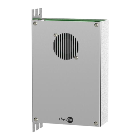
7 Mounting Mounting inverter e@syDrive 4330 The inverter must be fixed with 4x M3 screws. ATTENTION Bottom surface must be protected against short circuit! (No contact to electrically conductive materials.) → Recommendation: mount inverter onto distance-pins > = 5 mm length. Mounting inverter e@syDrive 4330-H The inverter can be fixed with up to 4 Screws. -
Page 19: Connection Example
12 months from the date of sale certified by the vendor. In the event of justifiable complaints, SycoTec shall supply spare parts or carry out repairs free of charge under warranty. SycoTec accepts no liability for defects and their consequences which have arisen or could have arisen as... - Page 20 (EN = original)
Need help?
Do you have a question about the easyDrive 4330 IP00 and is the answer not in the manual?
Questions and answers