Table of Contents
Advertisement
Quick Links
UNPACKING INSTRUCTIONS
Carefully open the carton, remove contents and lay out on cardboard or other protective surface to avoid damage.
Check package contents against the Supplied Parts List in the next page to assure that all components were
received undamaged. Do not use damaged or defective parts.
Carefully read all instructions before attempting installation.
IMPORTANT SAFETY INFORMATION
Install and operate this device with care. Please read this instruction before beginning the installation, and carefully
follow all instructions contained herein. Use proper safety equipment during installation.
Please call a qualified installation contractor for help if you:
If you don't understand these directions or have any doubts about the safety of the installation.
If you are uncertain about the nature of your wall, consult a qualified installation contractor.
Do not use this product for any purpose or in any configuration not explicitly specified in this instruction. We hereby
disclaim any and all liability for injury or damage arising from incorrect assembly, incorrect mounting, or incorrect use
of this product.
!
WARNING
Tools Required
Note:
The mounting components and hardware supplied in this package are not designed for installations to walls with steel studs or
to cinder block walls. If the hardware you need for your installation is not included, please consult your local hardware store for proper
mounting hardware for the application.
Installation Instruction
This TV mount must be securely attached to the vertical wall. If the
mount is not properly installed it may fall, resulting in possible injury
and/or damage.
4mm Drill Bit
Phillips Screwdriver
CAUTION!
10mm Masonry Bit
Stud Finder
1
English
CT130E
Wrench or Socket Set
Carpenter's Level
Advertisement
Table of Contents

Related Manuals for BONTEC CT130E


Summary of Contents for BONTEC CT130E
- Page 1 English Installation Instruction CT130E UNPACKING INSTRUCTIONS Carefully open the carton, remove contents and lay out on cardboard or other protective surface to avoid damage. Check package contents against the Supplied Parts List in the next page to assure that all components were received undamaged.
- Page 2 Supplied Parts List A (x1) B (x1) C (x2) D (x2) E (x8) F (x8) G (x1) M4x12 (x4) M4x30 (x4) M6x15 (x4) M6x30 (x4) M8x20 (x4) M8x50 (x4) 5mm (x8) 10mm (x8) D6 Washers D8 Washers bubble level (x1) Cable tie (x5) HDML cable (x1) M-I (x4)
- Page 3 Before getting started, let's make sure this mount is perfect for you! 1. Is your TV VESA equal to/greater than 75x75mm and equal to/less than 400x400mm? MAX:400mm Yes --- Perfect! MAX:400mm No --- This mount is NOT compatible. 2. What is your wall made of? 16"...
- Page 4 Step 3 Select monitor plate configuration Select the configuration A,B,C,D,or E to use based on the measurement from STEP 2. 200mm VESA Pattern VESA Pattern 100mm Configuration Configuration (WxH) (WxH) 75mm 75mmx75mm 300mmx200mm 100mmx100mm 300mmx300mm 200mmx100mm 400mmx200mm 200mmx200mm 400mmx300mm 400mmx400mm 200mmx300mm 200mmx400mm 200mm...
- Page 5 Step 4 lnstall VESA Plate to the back of TV Assemble monitor plate and extenders Manual Only! For Flat screen TV 2.1 G/H/J/K/L/M/N 2.2 A/B/C (Optional) M-B/D M-C/E For Curved TV M-B/D...
- Page 6 Step 5-1 Mounting the Wall Plate to the Wall Wood Studs Wall 70mm...
- Page 7 Step 5-2 Mounting the Wall Plate to the Wall Brick or Concrete Wall 70mm 60mm 10mm Step 6 Lift and hang TV with brackets onto wall bracket.
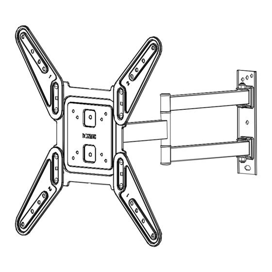
- Page 8 Step 7 Lift and hang TV with brackets onto wall bracket. Tilting +10° /-10° Leveling +3° /-3° Product dimensions: Step 8 400mm 470mm 300mm +10° -10° 60mm Thank you for choosing our products.
Need help?
Do you have a question about the CT130E and is the answer not in the manual?
Questions and answers