Advertisement
Table of Contents
- 1 Unpacking Instructions
- 2 Supplied Parts List
- 3 Connecting the Support Column to Tempered Glass
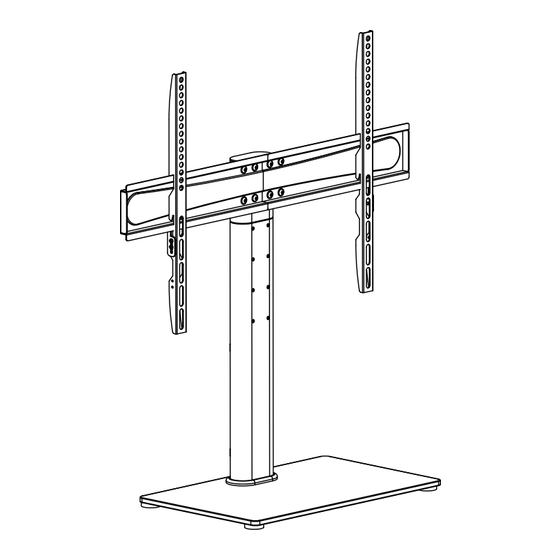
- 4 Connecting the TV Plate to Support Column
- 5 Mounting the Monitor Brackets to a TV
- 6 Attaching the TV to TV Plate and Managing the Wires
- 7 Attaching the Security Steel Wire to the TV
- Download this manual
Carefully open the carton, remove contents and lay out on cardboard or other protective surface to avoid damage.
!
Check package contents against the Supplied Parts List in the next page to assure that all components were received
!
undamaged. Do not use damaged or defective parts.
Carefully read all instructions before attempting installation.
!
Install and operate this device with care. Please read this instruction before beginning the installation, and carefully
follow all instructions contained herein. Use proper safety equipment during installation.
Please call a qualified installation contractor for help if you:
If you don't understand these directions or have any doubts about the safety of the installation.
!
If you are uncertain about the nature of your wall, consult a qualified installation contractor.
!
Do not use this product for any purpose or in any configuration not explicitly specified in this instruction. We hereby
disclaim any and all liability for injury or damage arising from incorrect assembly, incorrect mounting, or incorrect use of
this product.
1
Advertisement
Table of Contents

Related Manuals for BONTEC ST 13


Summary of Contents for BONTEC ST 13
- Page 1 Carefully open the carton, remove contents and lay out on cardboard or other protective surface to avoid damage. Check package contents against the Supplied Parts List in the next page to assure that all components were received undamaged.
- Page 2 (2)TV Plate-a1 (1)TV Plate-a2 (2)Monitor Bracket-b (1)Tempered Glass-c (1)Support Column-d1 (1)Support Column-d2 (1)Plastic Socket-e (1)Metal Pad-f1 (1)Soft Pad-f2 (8)Metal Washer-h1 (2)Metal Washer-h2 (10)M6x10 Bolt-g (3)M8x22 Bolt-i (2)Wire Clip-j M6X10 Ø6.5 * Ø18 * 2.0 (4)Rubber Foot-k (4)M4x12 Bolt-l (4)M4x30 Bolt-m (4)M6x20 Bolt-n (4)M6x35 Bolt-o...
- Page 3 ...
- Page 4 g h1 Height Adjustable *TV Plate(a) can be installed on wall optionally, wall mounting hardware have not included.
- Page 5 First of all, make sure the diameter of the Bolt(l to q) your TV requires. Once you have determined the correct diameter, please see the diagram as below. You will thread the Bolt into the TV using the correct Washer(r,s,t), and using the spacer(u,v) if necessary.
- Page 6 If your TV is located nearby the wall as the Diagram 5a, then a steel wire can be attached for added security. Attaching the two ends of steel wire to the top two holes on the back of TV, shown in Diagram 5b. Wall Diagram 5a Diagram 5b...
Need help?
Do you have a question about the ST 13 and is the answer not in the manual?
Questions and answers