
Subscribe to Our Youtube Channel
Related Manuals for Lincoln Electric INVERTEC 161S


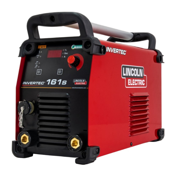
Summary of Contents for Lincoln Electric INVERTEC 161S
- Page 1 SVM 3152 Rev.00 04-2021 ® INVERTEC 161S For use with machines having code numbers: 50572 LINCOLN ELECTRIC EUROPE www.lincolnelectric.eu...
-
Page 2: Table Of Contents
INDEX OF CONTENTS TECHNICAL SPECIFICATIONS ............................. 2 Installation and Operator Instructions ..........................7 REPAIR PROCEDURE- MAIN TEST POINTS ......................12 CALIBRATION ................................13 1 TEST EQUIPMENT SETUP ............................15 2 OFF LINE GENERAL CHECK ............................ 16 3 OFF LINE PFC CHECK .............................. 17 4 OFF LINE PFC CHECK (shutdown network) ...................... -
Page 3: Technical Specifications
TECHNICAL SPECIFICATIONS NAME INDEX INVERTEC ® 161S K14293-1 INPUT Input Voltage EMC Class Frequency 230 V ±10% 50Hz Single Phase Input Power at Rated Output Input Amperes I 1max 7.3kVA @ 100% Duty Cycle (40°C) 21 A 5.4kVA @ 30% Duty Cycle (40°C) 21 A RATED OUTPUT AT 40°C Duty Cycle... - Page 4 ECO design information The equipment has been designed in order to be compliant with the Directive 2009/125/EC and the Regulation 2019/1784/EU. Efficiency and idle power consumption: Efficiency when max power Index Name Equivalent model consumption / Idle power consumption K14293-1 INVERTEC ®...
- Page 5 Typical gas usage for MIG/MAG equipment: DC electrode positive Wire Wire Feeding Gas flow Material type diameter Shielding Gas Current Voltage [m/min] [l/min] [mm] Carbon, low 0,9 ÷ 1,1 95 ÷ 200 18 ÷ 22 3,5 – 6,5 Ar 75%, CO alloy steel Aluminium 0,8 ÷...
- Page 6 If any electromagnetic disturbances are detected the operator must put in place corrective actions to eliminate these disturbances with, if necessary, assistance from Lincoln Electric. This equipment is compliant with EN 61000-3-12 and EN 61000-3-11.
- Page 7 Failure to follow the instructions in this manual could cause serious personal injury, loss of life, or damage to this equipment. Read and understand the following explanations of the warning symbols. Lincoln Electric is not responsible for damages caused by improper installation, improper care or abnormal operation.
- Page 8 WELDING SPARKS CAN CAUSE FIRE OR EXPLOSION: Remove fire hazards from the welding area and have a fire extinguisher readily available. Welding sparks and hot materials from the welding process can easily go through small cracks and openings to adjacent areas. Do not weld on any tanks, drums, containers, or material until the proper steps have been taken to insure that no flammable or toxic vapors will be present.
-
Page 9: Installation And Operator Instructions
Intoduction ® General description The welding machines INVERTEC 161S enables welding: The system consists of a modern direct current SMAW (MMA) generator for the welding of metals, developed via GTAW (arc ignition using lift TIG) application of the inverter. This special technology allows for the construction of compact light weight generators Recommended equipment, which can be bought by with high performance. - Page 10 Fault in supply/control stage. Contact Technical Assistance. WARNING The welding machine can be supplied from a power Power converter overtemperature generator of output power at least 30% larger than input due to excessive work cycle. power of the welding machine. Stop welding and leave the (Thermal alarm) See "Technical Specifications"...
- Page 11 WARNING The generator has an antisticking device that disables the ower in case of output short circuit or sticking of the electrode, thus allowing the electrode to easily detach from the workpiece. This device cuts in when the generator is powered, hence also during the initial test period, therefore any inclusion of load or short circuit in this period is seen as an anomaly that causes disabling of output power (the message “ScA”...
- Page 12 spatter. Maintenance WARNING Welding GTAW Process For any repair operations, modifications or maintenances, INVERTEC ® 161S can be used to GTAW process with it is recommended to contact the nearest Technical DC (-). Arc ignition can be achieved only by lift TIG Service Center Lincoln...
- Page 13 Types of malfunctioning/ welding faults – causes – remedies Table 3 Types of malfunctioning welding Possible causes Controls and remedies faults The main switch is off. Turn the main switch on. Power cable interrupted (two or Check and remedy.
-
Page 14: Repair Procedure- Main Test Points
REPAIR PROCEDURE- MAIN TEST POINTS... -
Page 15: Calibration
CALIBRATION 1.0 SUBSTITUTION OF THE CONTROL PCB Every time the electronic control board has to be replaced, the following calibration procedure has to be followed 1. The new circuit has to be connected and set up on the new machine 2. - Page 16 CALIBRATION 1.2 CALIBRATING MINIMUM CURRENT. 1. Press key T2. 2. The display reads out „5“ (the minimum calibration current). 3. Adjust the control panel encoder to set an output current of 5.0 (-0.8, -0.2) A dc. Output current is set to 5.0 (-0.8, -0.2) A dc. 1.3 AUTOCALIBRATING THE REMOTE CHANNEL AND DATA MEMORISATION 1.
-
Page 17: Test Equipment Setup
1 TEST EQUIPMENT SETUP 1) Place an ultrafast protection diode between TP6 (+15V) and TP27 (PFC_V). Use an 1A 600V rectifier (BYV26C) and dispose the anode on TP6. 2) Place a 22ohm 10W resistor between M1-1 (+FAN) and M1-2 (-FAN). To avoid errors on the acquired voltage, the better solution is to reserve TP7 for the voltage reading only. -
Page 18: Off Line General Check
2 OFF LINE GENERAL CHECK Connect a suitable source of regulated voltage 15,3 V dc (tolerance +/- 0,30Vdc ≈ 1.2 Amp of limiting current) between the TP6 (+15V) and grounding plane (GND1). Perform the following operations: Relay status (opened). Verify the TP7 voltage immediately after power-on (≥ 14,1 V ... -
Page 19: Off Line Pfc Check
3 OFF LINE PFC CHECK Connect a 39 Kohm, 5% resistor between TP57 (VREF) and TP55. Note: to limit the noise, this resistor has to be placed near TP55 Proceed with the following test: PFC Activity (QP1 and QP2 gate). Acquire the gate waveform on the power switches (TP45 and TP53). -
Page 20: Off Line Inverter Check
5 Off Line Inverter Check Connect a 3K9, 5% resistor between TP57 (VREF) and TP58 (VFB). Using a suitable differential probe, proceed with the following tests: SW1 gate WF. Acquire the gate waveform on TP64 with respect TP67. SW2 gate WF. Acquire the gate waveform on TP65 with respect TP66. ... -
Page 21: On Line Auxiliary Power Supply And Interface Connector Check
6 ON LINE AUXILIARY POWER SUPPLY AND INTERFACE CONNECTOR CHECK Remove short-circuit between CFG_2 and GND1 (in order to enable the auto-test routine) Remove the 39K resistor between TP57 (VREF) and TP55. Disconnect the source of regulated voltage 15,3 V dc (main Supply). Note: The 3K9 resistor between TP57 (VREF) and TP58 (VFB) has to remain connected. -
Page 22: On Line Board Auto_Test And Other Tests
7 ON LINE BOARD AUTO_TEST AND OTHER TESTS Reconnect the nominal power supply voltage (230Vac +/- 5% – 50Hz) between the pins PZ1 and PZ2. Await a split second. Connect a source of regulated DC voltage (3,4 – 5,0 V dc) to TP11 (SER_IN input) with respect CGND Await about five seconds (until RED led is on) for the Board Auto-test (Note 1). -
Page 23: On Line Test (Inverter No Load Check)
8 ON LINE TEST (Inverter No Load Check) Connect a source of regulated DC voltage (13,0 – 16, 0Vdc) to TP24 (CFG input) with respect CGND. Connect a source of regulated DC voltage (0,60Vdc +/- 2%) to TP20 (CUR_REF input) with respect CGND. -
Page 24: On Line Test (Inverter On Load Check)
9 ON LINE TEST (Inverter On Load Check) Warning. To avoid thermal protection action, the “ON Load Test” step (the following step) has to be closed in a maximum time of about 60 sec. In case of a failed measure, as first action, remove the controlling voltage from the PWR_EN input. -
Page 25: On Line Test (Current Transfer Ratio Selector Check)
10 ON LINE TEST (Current Transfer Ratio Selector Check) Remove the source of regulated DC voltage (13,0 – 16, 0V dc) from TP24 (or put it equal to 0,0V dc) Proceed with the following test: V_OUT. Verify the TP18 voltage (1,16 – 1,58 V dc) ... -
Page 26: End Of The Procedure
12 END OF THE PROCEDURE Remove all the measurement equipment connected to the PCB and remove the DUT. Auto-test Error Codes Error Pass Test Possible cause in case of Failed Test Code 14,0 V dc ≤ +15V ≤ 16,0 V dc Out of range +15V regulated supply. -
Page 27: Retest After Repair
Should a machine under test be rejected for any reason requiring the removal of any mechanical part that could affect the machine’s electrical characteristics, or if any electrical components are repaired or replaced, the machine must be retested. Machine input and output INVERTEC 161S Input Voltage Input Current Rated Output 230Vac ±10%... -
Page 28: Electrical Schematics
ELECTRICAL SCHEMATICS Block Diagram... -
Page 29: Power Circuit Board (R-6240-004-1R)
POWER CIRCUIT BOARD (R-6240-004-1R) -
Page 30: Front Panel Circuit Board (W000264772)
FRONT PANEL CIRCUIT BOARD (W000264772) -
Page 31: Circuit Board (W000275004)
CIRCUIT BOARD (W000275004) -
Page 32: Note
NOTE...
Need help?
Do you have a question about the INVERTEC 161S and is the answer not in the manual?
Questions and answers