
Related Manuals for Simpson 42112


Summary of Contents for Simpson 42112
- Page 1 Operating Instructions Wet Tensile Strength Tester Model 42112 www.simpsongroup.com...
- Page 2 Technologies Corporation or its subsidiaries which shall not be disclosed outside or duplicated, used or disclosed in whole or in part for any purpose other than to evaluate Simpson Technologies for a proposed transaction. Any use or disclosure in whole or in part of this information without the express written permission of Simpson Technologies Corporation is prohibited.
-
Page 3: Table Of Contents
Unpacking ..................12 Components ..................13 Installation ..................13 Electrical and Pneumatic Power Connection ........14 Connecting Power and Set-Up ............15 Airborne Noise Emission ..............16 Operating Instructions ............. 17 Preparing the Sand Specimen ............17 man-STC-42112-V17-3 Wet Tensile Strength Tester... - Page 4 Spare Parts List ................39 Ordering Replacement / Spare Parts ..........39 Returned Goods Policy ..............40 Decommissioning ..............41 10 Commercial Manuals ..............42 Instruction Delta Temperature Control DTB 4848 – Adjust Temperature 10.1 Wet Tensile Strength Tester man-STC-42112-V17-3...
-
Page 5: Introduction
Section 2 and operating instructions in Section 5. Application and Designated Use The Wet Tensile Strength Tester, Model 42112, determines tensile strength of the condensation zone that is created in all clay bonded molds during and after pouring. -
Page 6: Safety
Safety Signs and Labels Simpson Technologies has incorporated the ANSI Z535.6 / ISO 3864-1-2 safety symbol only label format on all of its laboratory equipment. For the location of the safety labels on your equipment, refer to the "Location of Nameplate and Decals"... -
Page 7: Safety Alert Symbols
This symbol indicates information containing important instructions concerning the use of the machine or directions for further procedures. Ignoring this information can lead to malfunction of the machine. man-STC-42112-V17-3 Wet Tensile Strength Tester... -
Page 8: Safety Symbol Labels
When the back panel is removed, electrical terminals are exposed. A hazardous voltage is present, can cause electric shock or burn, and will result in serious injury. Follow Lockout and Tagout procedures before servicing. Wet Tensile Strength Tester man-STC-42112-V17-3... - Page 9 Blown-out air with or without solid particles in the air stream may get into the eyes and may irritate or damage the eye. Follow Lockout and Tagout procedures before servicing. man-STC-42112-V17-3 Wet Tensile Strength Tester...
- Page 10 (STC #214042) This label is located on the front panel below the electronic control panel. Before operating and/or performing any maintenance or repair on Simpson Technologies Corporation designed and/or manufactured equipment, it is required that all personnel read and understand the entire Operating Instructions manual.
-
Page 11: Lockout And Tagout System Procedures
The tagout device does so by identifying the energy- isolating device as a source of potential danger; it indicates that the energy-isolating device and the equipment being controlled may not be operated until the tagout device is removed. man-STC-42112-V17-3 Wet Tensile Strength Tester... -
Page 12: Glossary
Zero Mechanical State - The mechanical potential energy of all portions of the equipment or machine is set so that the opening of pipes, tubes or hoses, and the actuation of any valve, lever or button, will not produce a movement which could cause injury. Wet Tensile Strength Tester man-STC-42112-V17-3... -
Page 13: Short Description & Specifications
The condensation zone is the lowest strength layer in the cross section of the mold and the source of casting defects. The Wet Tensile Strength Tester, Model 42112, is designed to measure the tensile strength of bentonite bonded molding sand in this condensation zone (wet layer. -
Page 14: Description
3 Short Description & Specifications Description The Wet Tensile Strength Tester, Model 42112, is designed to accurately determine the tensile strength of the condensation zone in a clay/bentonite bonded molding sand. The instrument recreates the casting environment by utilizing a heater to generate a condensation zone in a sand specimen. -
Page 15: Specifications, Dimensions And Weights (Approximate)
300 C and 320 C by means of a digital temperature controller. Specifications, Dimensions and Weights (Approximate) Specifications Wet Tensile Strength Tester (Model 42112) Length 455 mm (17.9 in.) Width 325 mm (12.7 in.) Height 480 mm (19 in.) Weight 50 kg (110 lbs.) -
Page 16: Unpacking And Installation
Damage should be noted on the shipper’s receipt before signing for receipt of the shipment. The Wet Tensile Strength Tester, Model 42112, is shipped in one piece and is intended to be used as received; no further assembly/disassembly is required. -
Page 17: Components
• Pneumatic Regulator/Filter • Pneumatic Hose and Connectors If any of the above components are missing, contact your local Simpson Technologies office. Do not store the device in the open and unprotected from atmospheric conditions. If this instruction is not followed, claims under guarantee will no longer be considered. -
Page 18: Electrical And Pneumatic Power Connection
Wet Tensile Strength Tester to the regulator/filter has been included with the Wet Tensile Strength Tester. The compressed air should be free of dirt, debris and condensate. Debris and condensate will cause damage to the Wet Tensile Strength Tester. Wet Tensile Strength Tester man-STC-42112-V17-3... -
Page 19: Connecting Power And Set-Up
(Figure 7-3, Item 8) located on the back side of the Wet Tensile Strength Tester. Secure the air hose to the air inlet with the provided connector that is attached to the air inlet. man-STC-42112-V17-3 Wet Tensile Strength Tester... -
Page 20: Airborne Noise Emission
Airborne Noise Emission Regarding airborne noise emission by the Wet Tensile Strength Tester (Model 42112), there is no motor or other noise emitted by this machinery other than the click of a solenoid valve being operated. As such, the equivalent continuous A-weighted sound pressure level at the workstation does not exceed 70db(A). -
Page 21: Operating Instructions
Operating Instructions For more information on how to use and care for your Simpson Analytics equipment and accessories visit our Simpson Technologies channel on YouTube and search our library of videos. Subscribe to our channel to keep updated on new releases. - Page 22 Failure to use a Simpson Technologies Corporation manufactured Sand Rammer or Sand Squeezer may result in damage to the specimen tube base or specimen tube assembly.
-
Page 23: Performing A Wet Tensile Strength Test
Set button on the temperature controller to enter this value. The set point (SV) temperature should be set at 310 (590 For further information regarding the temperature controller, refer to the temperature controller manufacturer’s manual in Section 11 of this manual. man-STC-42112-V17-3 Wet Tensile Strength Tester... - Page 24 The flange of the detachable ring should be above the top of the fork and below the heating plate during this operation. Wet Tensile Strength Tester man-STC-42112-V17-3...
- Page 25 (Figure 7-1, Item 2). At the same time, the Operation Finished indicator (Figure 7-1, Item 5) turns on, indicating that the wet tensile strength test is complete. The three digit unit of measure value displayed in the load display is in man-STC-42112-V17-3 Wet Tensile Strength Tester...
-
Page 26: Error Messages
The following list shows all potential error messages that may occur in the load display. The list provides basic definitions and potential causes and solutions for each error message of the Wet Tensile Strength Tester: Wet Tensile Strength Tester man-STC-42112-V17-3... - Page 27 If the status of the measuring fork appears normal, then this message may indicate a failure in the electronic circuit. Contact Simpson Technologies for additional assistance in resolving this message. •...
-
Page 28: Maintenance And Calibration
Maintenance and Calibration For more information on how to use and care for your Simpson Analytics equipment and accessories visit our Simpson Technologies channel on YouTube and search our library of videos. Subscribe to our channel to keep updated on new releases. -
Page 29: Replacing Oil In Hydro-Pneumatic Oil System
13. Using a syringe equipped with a thick needle, slowly refill the oil back into the hydro-pneumatic system from the oil inlet connectors. Continue to add oil until excessive oil flows out of oil inlet connectors. man-STC-42112-V17-3 Wet Tensile Strength Tester... -
Page 30: Calibration
Wet Tensile Strength Test” for detailed procedures on programming heating time). 4. Zero the load display (see Section 5.2 “Performing a Wet Tensile Strength Test” for detailed procedures on how to zero load display) 5. Press the button to begin a test. Wet Tensile Strength Tester man-STC-42112-V17-3... -
Page 31: Determining Proper Heating Time
Position 2 would be considered the correct heating time. Position 1 would be considered an excessive heating time and Position 3 would be considered insufficient heating time. Typically, the proper sand specimen heating time will result in the lowest wet tensile strength man-STC-42112-V17-3 Wet Tensile Strength Tester... -
Page 32: Heating Plate Temperature
3. Note the weight of the Master Calibration Weight from the calibration certificate. 4. Gently place a Master Calibration Weight, Model 42112B, on the measuring fork (Figure 7-2, Item 2). See Photo 1 showing the Master Calibration Weight loaded onto the measuring fork. Wet Tensile Strength Tester man-STC-42112-V17-3... - Page 33 6. The load display (Figure 7-1, Item 2) should read 00. If not, then repeat Steps 2 through 6 until the load display indicates 00 after the Master Calibration Weight is removed from the measuring fork. man-STC-42112-V17-3 Wet Tensile Strength Tester...
-
Page 34: Measuring Fork Alignment
7. If the alignment tube tilts (leans) to the left or right, then carefully adjust the position of the support pins on the measuring fork to correct the alignment. 8. If the alignment tube tilts (leans) backward or forward, then contact Simpson Technologies for support. Wet Tensile Strength Tester man-STC-42112-V17-3... -
Page 35: Apparatus Layout And Location Of Safety Symbols
Apparatus Layout and Location of Safety Symbols Apparatus Layout and Location of Safety Symbols Figure 7-1 - Electronic Panel man-STC-42112-V17-3 Wet Tensile Strength Tester... - Page 36 Tensile Strength Load Display Ready to Start Indicator Timer On Indicator Light Operation Finished Indicator Start Button Clear Tensile Display Zero Tensile Display Numeric Key Pad Clear Time Button Calibration Span Calibration Zero Time Symbol Tensile Strength Symbol Wet Tensile Strength Tester man-STC-42112-V17-3...
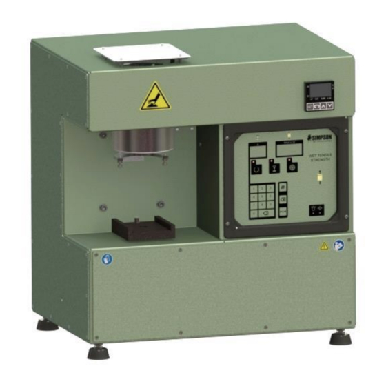
- Page 37 Apparatus Layout and Location of Safety Symbols Figure 7-2 - Front View Item Apparatus Description Heating Plate Measuring Fork Table Front Control Panel Temperature Controls (See Section 10.1 for operating instructions) man-STC-42112-V17-3 Wet Tensile Strength Tester...
- Page 38 Apparatus Layout and Location of Safety Symbols Figure 7-3 - Rear View Item Apparatus Description ON/OFF Switch Air Exhaust Compressed Air Inlet Oil Inlet Connector Oil Draining Connector Power Cord Receptacle Wet Tensile Strength Tester man-STC-42112-V17-3...
- Page 39 Apparatus Layout and Location of Safety Symbols Figure 7-4 - Top View Item Apparatus Description Heat Vent Cover man-STC-42112-V17-3 Wet Tensile Strength Tester...
- Page 40 Apparatus Layout and Location of Safety Symbols Figure 7-5 - Left Side View Item Apparatus Description Table Speed Regulating Valve Wet Tensile Strength Tester man-STC-42112-V17-3...
- Page 41 Apparatus Layout and Location of Safety Symbols Figure 7-6 - Front View Item Item Safety Symbol Description Safety Burn Hazard - Hot Surface Wear Gloves/Avoid Burn Read and Understand All Service Manual Instructions Electrical Shock/Electrocution man-STC-42112-V17-3 Wet Tensile Strength Tester...
- Page 42 Apparatus Layout and Location of Safety Symbols Figure 7-7 - Rear View Item Safety Symbol Description Equipment Name Plate (Supplied with Tester) Explosion/Release of Pressure Electrical Shock/Electrocution Wet Tensile Strength Tester man-STC-42112-V17-3...
-
Page 43: Parts List / Ordering Parts / Returns 8
Parts List / Ordering Parts / Returns Spare Parts List Simpson maintains a large inventory of common spare parts for all current Simpson Analytics products. The following table provides part numbers for common spare parts for this device. Contact Simpson Technologies with the part number and description when ordering. -
Page 44: Returned Goods Policy
The material being returned must be identified and the reason for its return clearly specified. Once approved for return, Simpson Technologies will issue the customer an RMA form to be included with the shipment and with instructions on where and how to ship the goods. -
Page 45: Decommissioning
Parts List / Ordering Parts / Returns 8 Decommissioning Before doing work, review Safety Procedures in Section 2 and Lockout and Tagout all the power sources to the machine and peripheral equipment! Failure to follow safety procedures could result in serious injury. -
Page 46: Commercial Manuals
10 Commercial Manuals Commercial Manuals Instruction Delta Temperature Control DTB 4848 – Adjust 10.1 Temperature 1. Turn on power switch of the equipment. 2. The Temperature Default is in °C. 3. To change the temperature Set Value “SV”, press either UP or DOWN arrow (Figure 10-1, Item 5). - Page 47 Commercial Manuals 10 Item Description “PV” Process Value (Actual Temperature) “SV” Set Value (Desired Temperature) “SET” button, Use it to Save the Changes. Select “FUNCTION” Button UP and DOWN Arrow Buttons Display Window (SV & PV) man-STC-42112V17-3 Wet Tensile Strength Tester...
- Page 48 Fax: +91 (33) 2290 8050 simpsongroup.com Copyright 2021. All rights reserved. SIMPSON, the illustrative logo and all other trademarks indicated as such herein are registered trademarks of Simpson Technologies Corporation. For illustrative purposes the Simpson equipment may be shown without any warning labels and with some of the protective devices removed. The warning labels and guards must always be in place when the equipment is in use.
Need help?
Do you have a question about the 42112 and is the answer not in the manual?
Questions and answers