Table of Contents
Advertisement
Quick Links
Excerpt from Moog
L180 Programmable Servodrives
Installation and User's Manual
Revision b 5/00
This is a portion of a user's manual made available in segments on the website for the
convenience of our customers. If you have questions or need additional information please
contact us.
This manual describes the functionality and features of the present version of the L180
Product Family. Not all of the described features are available in previous versions of
theL180 Servodrive.
Information contained herein is subject to change without notification and should not be construed
as a commitment by Moog Inc. This manual is periodically reviewed and revised. Moog Inc.
assumes no responsibility for any errors or omissions in this document. Critical evaluation of the
manual by the user is welcomed. Your comments will assist us in future product documentation.
Copyright 2000 by Moog Inc. All rights reserved.
.
Moog Inc., Electric Drives Group
Regional Centers:
USA: +716-655-3000
Germany +49-7031-622-0
Italy +39-010-96711
Japan: +81-463-55-3615
See
www.moog.com
to find the location nearest you.
Advertisement
Table of Contents

Subscribe to Our Youtube Channel
Related Manuals for Moog L180


Summary of Contents for Moog L180
- Page 1 If you have questions or need additional information please contact us. This manual describes the functionality and features of the present version of the L180 Product Family. Not all of the described features are available in previous versions of theL180 Servodrive.
-
Page 2: Installation
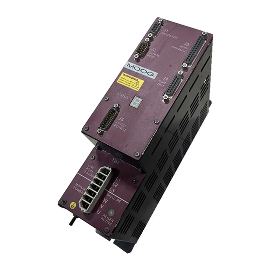
NSTALLATION NSTALLATION This chapter on installation refers to L180 servo drives series. The wiring of the L180 servo drive must be carried out according to the schematics in these instructions. Local wiring regulation must be observed. Special attention should be paid with respect to wiring rules regarding ground, earth and neutral. - Page 3 L180 User's Manual NSTALLATION 4.2 C ONNECTOR VERVIEW J1 RESOLVER J3 AXIS SIGNALS Terminal for resolver Analog Input cable Digital Input/Output Status Relay Contact J2 SERIAL PORT RS 232 Interface J4 ESM OUT Differential encoder output signals from RS422 line driver, A, ,...
- Page 4 L180 User's Manual NSTALLATION 4.2.1 OTOR AND OWER CONNECTOR The servo drive unit can be operated with either a single-phase or three-phase AC voltage. Table 18: Main line voltage Unit Minimum Regular Maximum Mains frequency 50/60 Supply Voltage WARNING A three phase automatic circuit breaker must be used for three phase operation in order to ensure that all phases are tripped at the same time in the event of a fault! The wire protection must be taken into account.
- Page 5 Brake The brake is released with 24 VDC. This voltage must be provided and controlled by an auxiliary power supply. The L180 servo drive does not support any brake control. The brake is designed for static holding applications where the shaft is held during disabling of the drive. If the brake is used for dynamic braking several times, it will become worn and the braking effect will deteriorate.
- Page 6 L180 User's Manual NSTALLATION WARNING The motor must be wired and tested consistent to this manual. • Power cable An incorrect phase sequence can cause the motor to accelerate in an uncontrolled manner upon enabling the drive. Sufficient line filter for a single axis application is shown in the table below.
- Page 7 L180 User's Manual NSTALLATION 4.2.1.1 POWER CONNECTOR PINOUT Table 20: TB1 power connector pinout MOOG motors pin number TB1 power connector Gxx2, Gxx3, pin number pin name function pin type G4x5 Gxx4 main line terminal L1,L2,L3 L1,L2,L3 power input 3~ 230 VAC...
- Page 8 L180 User's Manual NSTALLATION Table 21: Accessory parts power connector Description Part Part Number Motor Drive mating power C08474-001 all drives Mating power connector for all connector drives. Supplied with each drive, spare part. Type Weidmueller STVS 7 SB, cross-sectional area 0.5 - 4 mm², 20 - 12 AWG.
- Page 9 L180 User's Manual NSTALLATION 4.2.2 ESOLVER ONNECTOR Correct wiring of the resolver is necessary for reliable operation of the L180 servo drive. Non- compliance with the instructions in this manual will cause a deterioration of specified performance. Standard Alternative colors...
- Page 10 L180 User's Manual NSTALLATION WARNING The motor must be wired and tested consistent to this manual. • Signal cable Incorrect connection of the leads can cause the motor to accelerate in an uncontrolled manner when the drive is enabled. Any broken wire of the NTC connection means a loss of the thermal motor protection.
-
Page 11: Serial Port Connector
L180 User's Manual NSTALLATION 4.2.3 ERIAL ONNECTOR The serial link is used to set or monitor drive parameters stored in non-volatile memory using the configuration program. The serial link can also be used to perform firmware revisions. white RXD 2... -
Page 12: Specification
L180 User's Manual NSTALLATION 4.2.4 XIS SIGNALS ONNECTOR GND24V ANALOG IN- ± 10 VDC ENABLE24V variable ANALOG IN+ Enable Switch Voltage Source 24VDC Power Supply AUTO/MANUAL Switch END-SW1 AUTO/MANUAL END-SW2 ALARM 24VDC Power Supply ALARM COM Input Enable Switch Host... - Page 13 ANALOG IN. The scaling of the analog input is programmable J3:3 ANALOG IN + in speed mode and fixed in current mode to the maximum drive current, e.g. 10VDC input on a L180-310A drive corresponds with 10 Arms. max, motor ±...
-
Page 14: Encoder Simulation
Only the ANALOG IN input and one of the Enable options have to be connected to operate the drive, other functions are programmable in the L180 GUI and can be set to values which make wiring unnecessary. Ground All pin ground’s are connected together with protective earth. The grounds in figure 44 J3 axis wiring are interchangeable and connected only to simplify the drawing layout. - Page 15 L180 User's Manual NSTALLATION clockwise rotation counterclockwise rotation Figure 46: Definition of Encoder Signals, viewed from the shaft side Cable The maximum cable length is 20m (66 ft). The exact cable length is dependent on cable routing and system noise. A shielded cable with twisted pair is recommended to lower the signal distortion.
-
Page 16: Logic Power Connector
L180 User's Manual NSTALLATION 4.2.6 OGIC OWER ONNECTOR 24V BACKUP 24V GND 24V BACKUP 24V GND 24 VDC Power Supply -15V OUT Reference Voltage could be used for ANALOG IN +15V OUT DSUB15 FEMALE Figure 47: J5 Logic Power Wiring, DSUB15 female cable to J5...
Need help?
Do you have a question about the L180 and is the answer not in the manual?
Questions and answers